
Ground hidden charging device used for new-energy automobiles

A new energy vehicle and charging device technology, applied in electric vehicle charging technology, charging stations, electric vehicles, etc., can solve the problems of reduced utilization rate, impact on appearance, and high cost of charging piles, and achieve reasonable structural design, high-efficiency protection, To achieve full utilization of the effect

Active Publication Date: 2018-06-15
长沙飞狐电动汽车充电服务有限公司
View PDF7 Cites 11 Cited by
  • Summary
  • Abstract
  • Description
  • Claims
  • Application Information

AI Technical Summary

Problems solved by technology

[0003] At present, pure electric vehicles have become the main force of new energy vehicles, and many public places have a large number of parking spaces equipped with charging piles. The cost of charging piles for electric vehicles is high and the maintenance costs are high, and most of the charging piles are open-air. Laying is easily damaged by exposure to sunlight and rain erosion, and the paint will fade and become old for a long time, which will affect the appearance. The open-air charging pile is also easy to be broken when reversing into the warehouse, causing huge social and economic losses. At the same time, each parking The location is equipped with an independent charging pile, which cannot charge other vehicles, which reduces the utilization rate, and cannot take into account the charging of the parking space after the charging pile is destroyed, resulting in idle resources

Method used


Image

  • Ground hidden charging device used for new-energy automobiles
  • Ground hidden charging device used for new-energy automobiles
  • Ground hidden charging device used for new-energy automobiles

Examples


Embodiment Construction

[0029] In order to make the technical means, creative features, goals and effects achieved by the present invention easy to understand, the present invention will be further elaborated below.

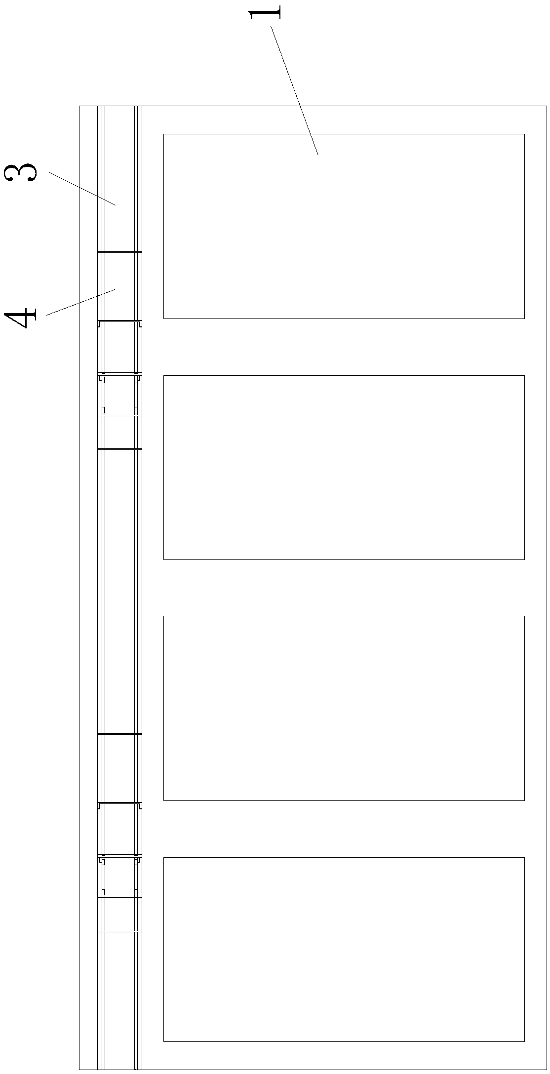
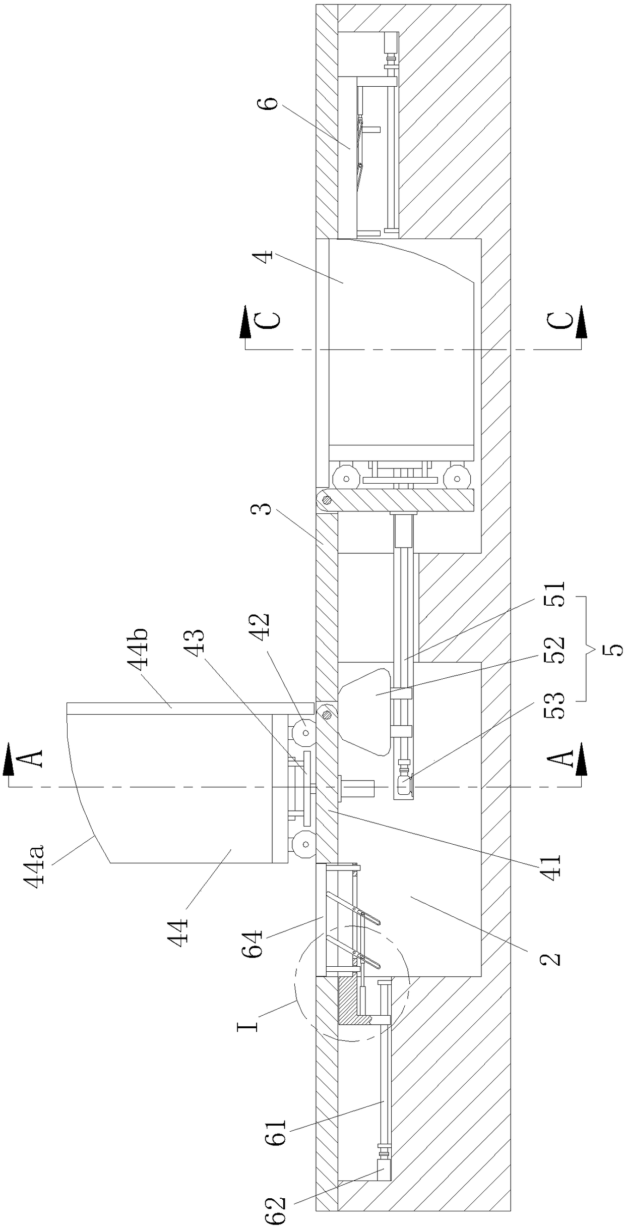
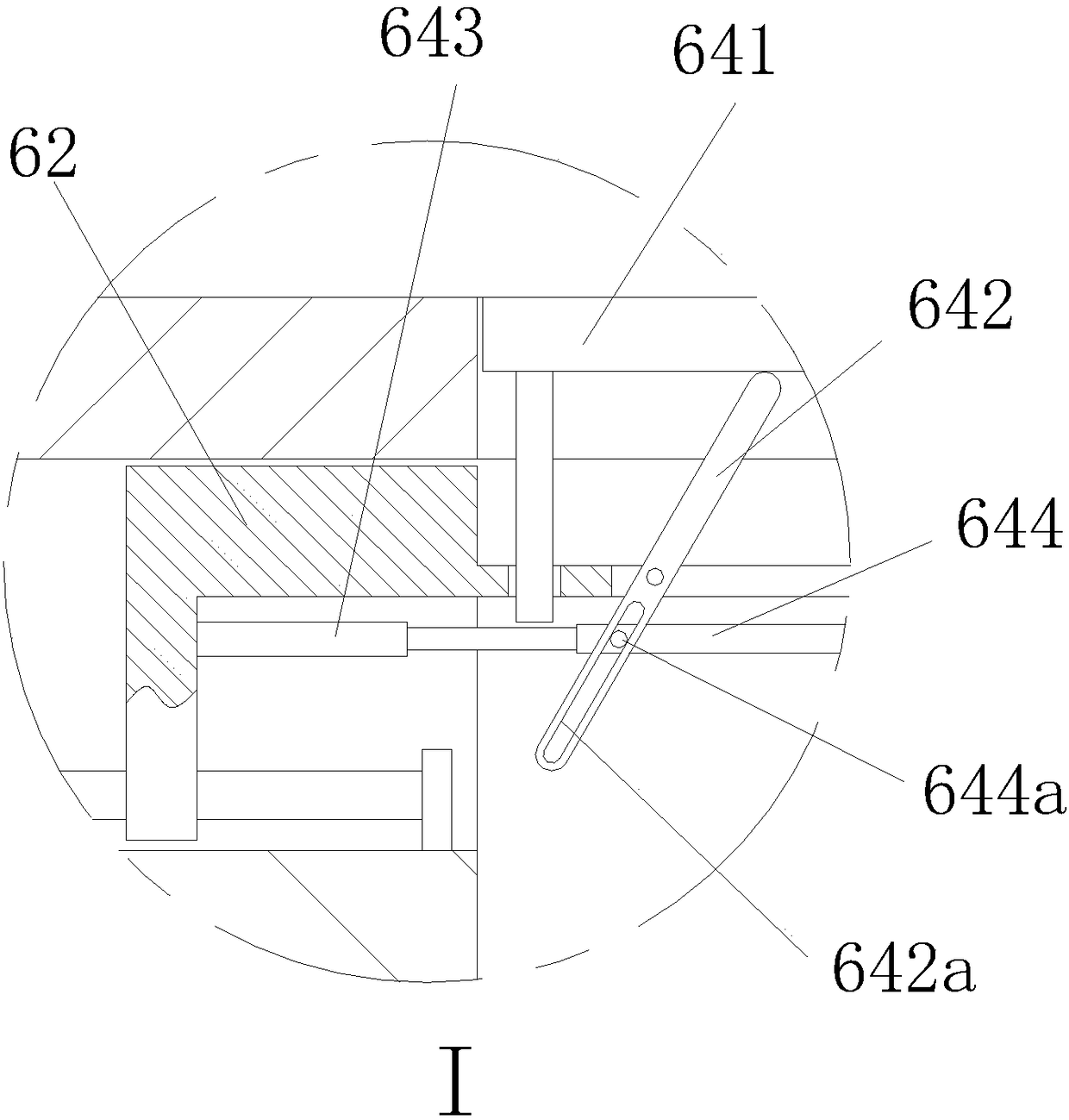
[0030] Such as Figure 1 to Figure 7 As shown, a charging device for ground hidden new energy vehicles includes a plurality of parking spaces 1 distributed in rows, and each parking space 1 is correspondingly provided with an installation slot 2 placed under the ground, and two adjacent Guide rails 3 are provided between the installation grooves 2, and a mobile charging mechanism 4 that is hingedly connected to the guide rails 3 is provided in the installation grooves 2. The installation grooves 2 are divided into two groups and are set as multiple groups, and each group is installed The slot 2 is provided with a drive mechanism 5 that pushes two adjacent mobile charging mechanisms 4 to turn upwards, and a shielding mechanism 6 that fills the gap between the installation slots 2 is prov...


PUM


Abstract

The invention relates to a ground hidden charging device used for new-energy automobiles. The ground hidden charging device comprises multiple parking spaces distributed in rows, each parking space iscorrespondingly provided with an installation groove formed underground, a guide rail is arranged between every two adjacent installation grooves, a movable charging mechanism hinged to the corresponding guide rail is arranged in each installation groove, every two installation grooves are arranged in a group, multiple groups of the installation grooves are arranged, a drive mechanism for pushingtwo adjacent movable charging mechanisms to be turned over upwards is arranged in the position of each group of the installation grooves, and sheltering mechanisms for filling gaps of the installation grooves are arranged below the guide rails; each movable charging mechanism comprises a turnover guide rail, a trolley, a clamping mechanism and a charging pile; and each sheltering mechanism comprises a second lead screw, a baffle, a second motor and a lifting guide rail. The hidden charging piles are adopted to achieve a protection effect, the charging piles are prevented from being damaged and broken after collisions and kept clean and tidy, the automobiles in different parking spaces can be charged, and the problem that the automobile cannot be charged in the corresponding parking spaceafter the corresponding charging pile is destroyed is solved.

Description

technical field [0001] The invention relates to the technical field of new energy vehicles, in particular to a ground-hidden charging device for new energy vehicles. Background technique [0002] With the vigorous development of society, people own more and more cars, and the fossil fuels stored on the earth are decreasing day by day. People will face the energy crisis of resource depletion. In order to reduce the consumption of fossil fuels, the development of new energy vehicles came into being . New energy vehicles refer to all other energy vehicles except gasoline and diesel engines. Its exhaust gas emission is relatively low, clean and less polluting. [0003] At present, pure electric vehicles have become the main force of new energy vehicles, and many public places have a large number of parking spaces equipped with charging piles. The cost of charging piles for electric vehicles is high and the maintenance costs are high, and most of the charging piles are open-air...

Claims


Application Information

Patent Timeline
Patent Type & Authority Applications(China)
IPC IPC(8): B60L11/18
CPCB60L53/31Y02T10/70Y02T10/7072Y02T90/12
Inventor 胡晓庆
Owner 长沙飞狐电动汽车充电服务有限公司
Learn More