A fuel tank production process and inflation device

A production process and oil tank technology, applied in the direction of providing/removing protective gas devices, manufacturing tools, metal processing equipment, etc., can solve problems such as fuel tank failures and splash failures, and meet the requirements of ensuring cleanliness, reducing splashes, The effect of reducing production costs

Active Publication Date: 2021-03-02
SHANTUI CONSTR MASCH CO LTD
View PDF5 Cites 0 Cited by
  • Summary
  • Abstract
  • Description
  • Claims
  • Application Information

AI Technical Summary

Problems solved by technology
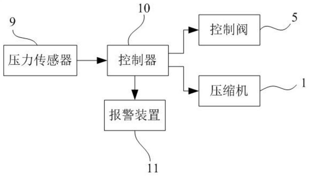
[0005] The purpose of the present invention is to propose a fuel tank production process and an inflation device, which can solve the problems in the prior art that the fuel tank is prone to malfunction caused by welding spatter and the spatter enters the hydraulic system from the fuel tank and causes malfunction

Method used


Image

  • A fuel tank production process and inflation device
  • A fuel tank production process and inflation device

Examples


Embodiment Construction

[0030] The technical solutions of the present invention will be further described below in conjunction with the accompanying drawings and through specific implementation methods.

[0031] This embodiment discloses a fuel tank production process, including the following steps:

[0032] Assemble boxes for processed plates before welding;

[0033] The hole on the fuel tank 7 to be welded is sealed;

[0034] Since the plate of the fuel tank 7 to be welded has holes connecting the fuel tank with other parts, all the holes are sealed before welding. The specific sealing method is to cover the holes with a cover plate and lock them with bolts. In order to enhance the sealing performance , There is a sealing ring between the cover plate and the edge of the hole to ensure that there is no air leakage at the opening. It can not only reduce air leakage for the subsequent inflation process, but also prevent spatter from entering the interior of the fuel tank through the opening to cause...


PUM


Abstract

The invention discloses a fuel tank production process and an inflation device, and relates to the technical field of fuel tank preparation. The fuel tank production process of the present invention includes: sealing the hole on the fuel tank to be welded; filling gas into the fuel tank to be welded, so that the fuel tank to be welded reaches the first preset pressure and maintains the pressure; using a mixture of argon and carbon dioxide gas The shielding gas is used for welding; after the welding is completed, the air pressure in the fuel tank is adjusted to the second preset pressure and maintained; the air tightness test is performed on the weld of the fuel tank. The inflation device of the present invention comprises a compressor and a pressure sensor arranged in the oil tank to be welded and a pressure gauge connected with the pressure sensor, an air bag is arranged on the pipeline between the compressor and the oil tank to be welded, and an air bag is arranged between the air bag and the oil tank to be welded. A control valve is provided. The invention fills the fuel tank to be welded with gas through the gas charging device before welding, which can prevent spatters from flying into the inner cavity of the fuel tank and ensure that the hydraulic system is not affected by the spatters during operation.

Description

technical field [0001] The invention relates to the technical field of fuel tank preparation, in particular to a fuel tank production process and an inflation device. Background technique [0002] The function of the hydraulic oil tank in the hydraulic system is mainly to store oil and dissipate heat, and also to separate gas and sediment in the oil. The hydraulic systems of excavators and full hydraulic bulldozers are all closed systems, which require high oil cleanliness. Especially for hydrostatic drive and electric drive bulldozers, the hydraulic components are mostly variable plungers and servo control units. The mechanical gap between them is small and is very sensitive to contamination. [0003] At present, the production of fuel tanks is welded by traditional carbon dioxide gas shielded welding, and carbon dioxide gas shielded welding itself has a large spatter, which will lead to serious burning of alloy elements in the deposited metal during welding, and poor mech...

Claims


Application Information

Patent Timeline
Patent Type & Authority Patents(China)
IPC IPC(8): B23K9/16B23K9/32
CPCB23K9/16B23K9/32B23K9/325
Inventor 翟浩黄亚军武永福孟令奎
Owner SHANTUI CONSTR MASCH CO LTD
Why Eureka
Try Eureka