
Subsoiler with plowing depth compensation mechanism

A compensation mechanism and subsoiler technology, which is applied in agricultural machinery and implements, soil preparation machinery, agriculture, etc., can solve the problem that subsoil ploughing depth is difficult to reach the predetermined ploughing depth, cannot completely break the bottom of the plough, and cannot achieve the expected subsoiling effect. and other problems, to achieve the effect of maintaining ploughing depth, improving the quality of subsoil operations, and reducing traction resistance

Active Publication Date: 2018-06-15
JILIN UNIV
View PDF7 Cites 0 Cited by
  • Summary
  • Abstract
  • Description
  • Claims
  • Application Information

AI Technical Summary

Problems solved by technology

[0003] The stability of tillage depth is an important indicator affecting the quality of subsoiling operations. In actual field operations, due to the influence of soil physical properties, machine operating speed, and surface flatness before plowing, it is difficult for subsoiling to reach the predetermined depth of tillage. , when the depth of subsoiling does not reach the predetermined depth of plowing, the bottom layer of the plow cannot be completely broken, so the expected effect of subsoiling cannot be achieved
Although a variety of technologies have emerged to control the depth of tillage, such as using sensors to detect the depth of tillage, using the suspension system of the tractor to adjust the depth of tillage, and controlling the depth of tillage by adding a depth-limiting wheel at the front of the subsoiler, etc. These methods still have shortcomings such as response lag and unstable control of tillage depth; in addition, after the current subsoiler detects that the tillage depth is not up to standard, it cannot take effective measures to compensate the tillage depth

Method used


Image

  • Subsoiler with plowing depth compensation mechanism
  • Subsoiler with plowing depth compensation mechanism
  • Subsoiler with plowing depth compensation mechanism

Examples


Embodiment Construction

[0020] The present invention is described below in conjunction with accompanying drawing.

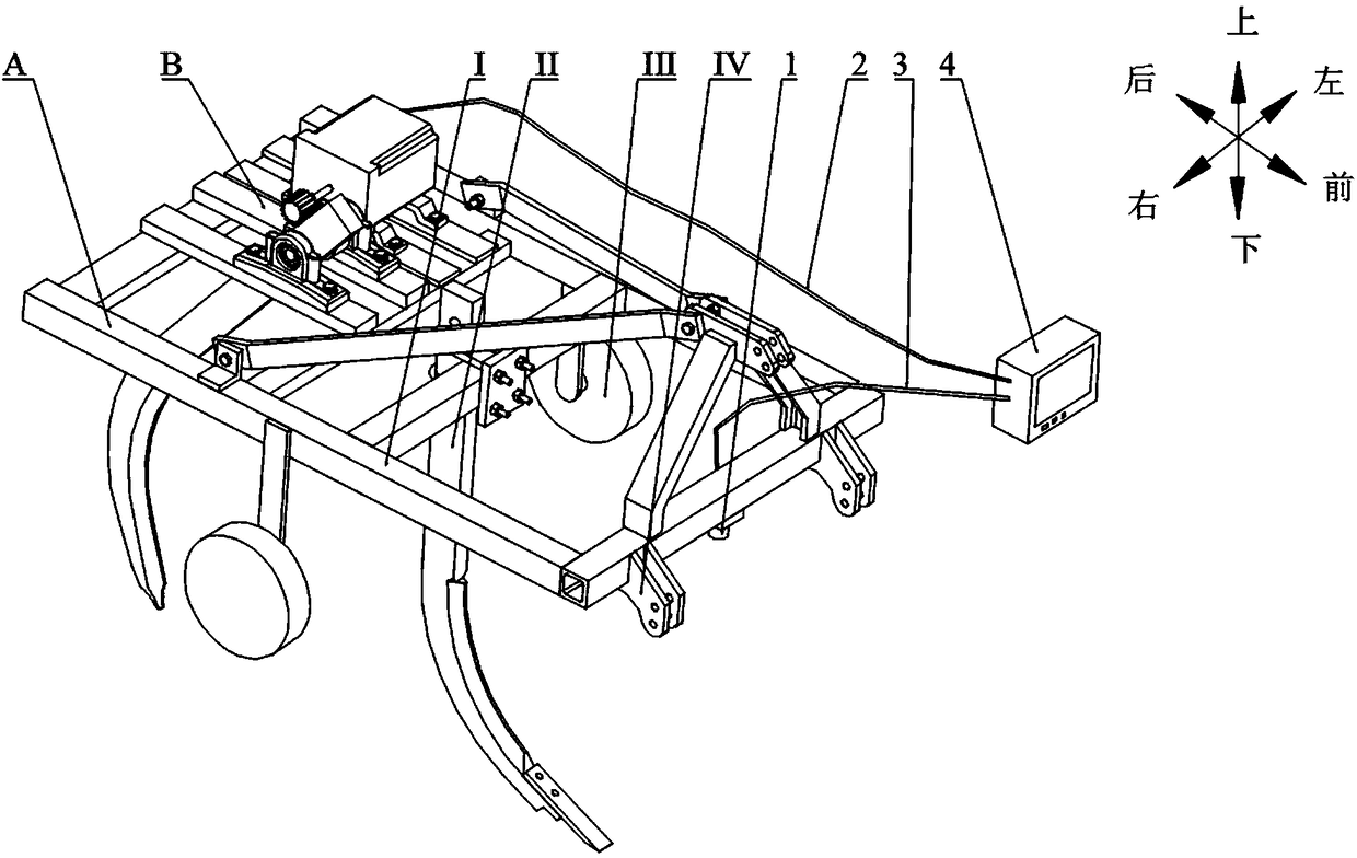
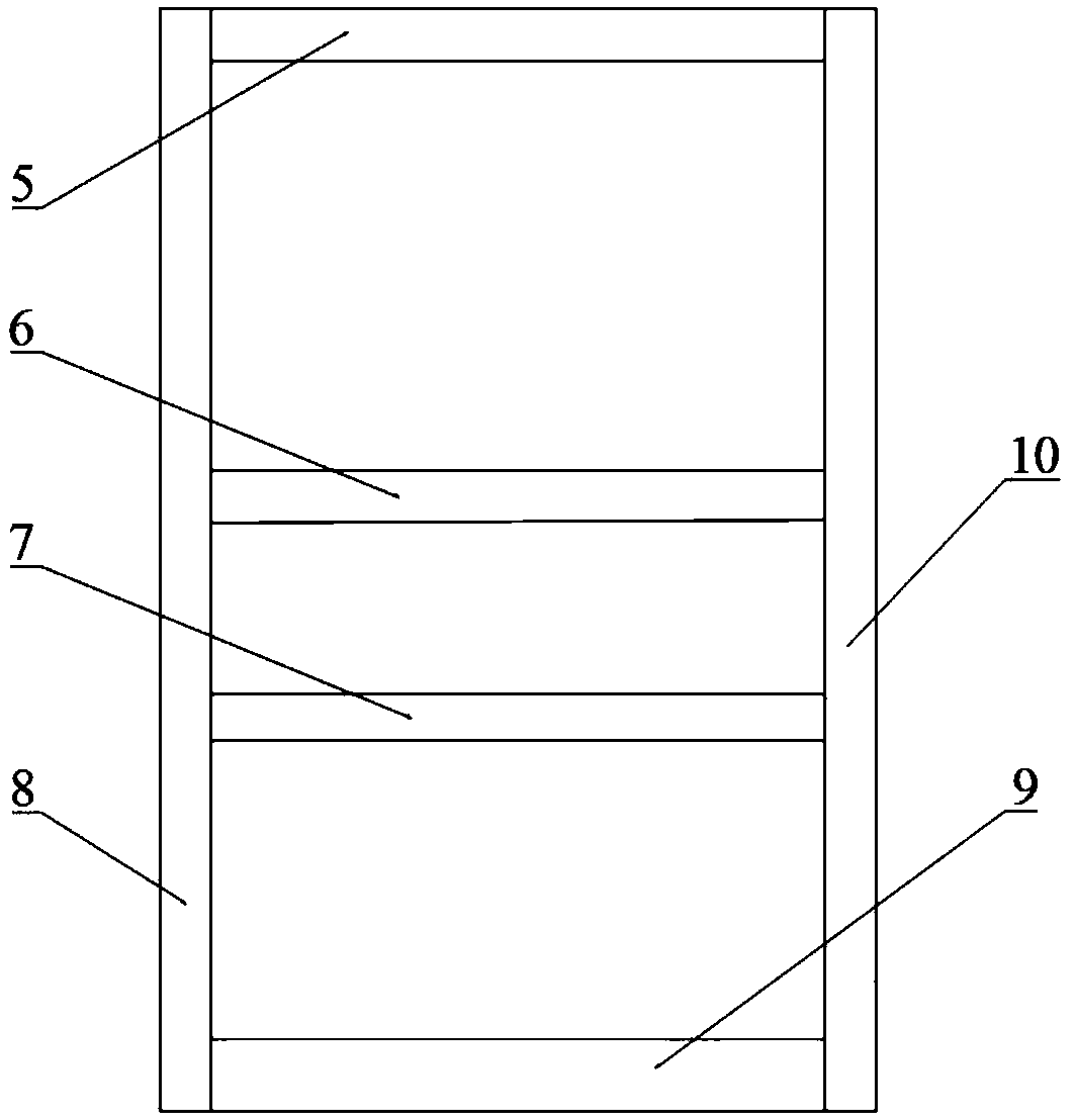
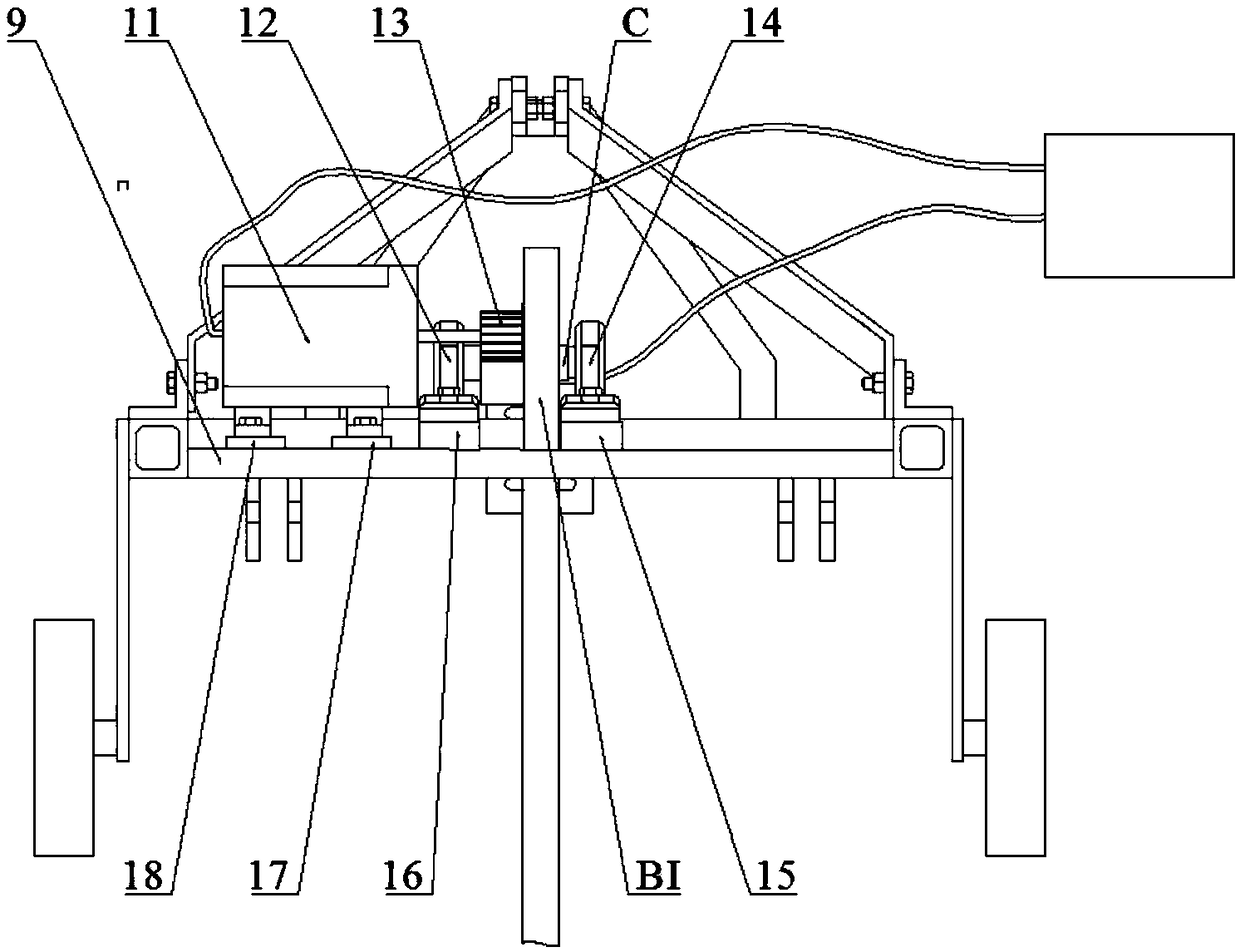
[0021] Such as figure 1 As shown, the present invention is composed of original subsoiler A, tillage depth compensation mechanism B, tillage depth sensor 1, wire I2, wire II3 and microcomputer 4; the original subsoiler A is composed of frame I, subsoiler Ⅱ. Depth limiting device Ⅲ and suspension device Ⅳ, in which frame Ⅰ is composed of front crossbeam 5, middle crossbeam Ⅰ6, middle crossbeam Ⅱ7, left longitudinal beam 8, rear crossbeam 9 and right longitudinal beam 10. figure 2 As shown, the front crossbeam 5, middle crossbeam I6, middle crossbeam II7 and rear crossbeam 9 are arranged in parallel in sequence, and the two ends of the front crossbeam 5, middle crossbeam I6, middle crossbeam II7 and rear crossbeam 9 are fixed to the left longitudinal beam 8 and the right longitudinal beam respectively. The inner side of the beam 10 is in the shape of "mesh"; the subsoiling device II is ...


PUM


Abstract

The invention provides a subsoiler with a plowing depth compensation mechanism and belongs to the technical field of agricultural machinery. A plowing depth compensation shovel of the plowing depth compensation mechanism is located behind a subsoiling device II, and four mounting plates of the plowing depth compensation mechanism are fixedly connected to the upper surface of a middle beam II and the upper surface of a back beam; a microcomputer installed in a tractor cab is connected with a stepping motor through a wire I, and the microcomputer is connected with a plowing depth sensor througha wire II; a gear wheel I of the plowing depth compensation mechanism is meshed with a gear wheel II of a shafting part; when plowing depth of the subsoiler doesn't reach the standard, the plowing depth compensation shovel is controlled by the stepping motor to achieve the preset plowing depth, plowing depth compensation is performed on land parcels with no standard plowing depth, as a result, theplow pan can be completely broken, and plowing depth is always in the preset plowing depth, thereby improving the plowing depth stability of the subsoiler and the quality of the subsoiling operation.

Description

technical field [0001] The invention belongs to the technical field of agricultural machinery, and in particular relates to a subsoiler with a tillage depth compensation mechanism. Background technique [0002] Due to long-term traditional farming and repeated rolling of farmland by agricultural machinery and tools, the soil structure in the farmland is destroyed and a solid plow bottom is formed. At the same time, due to excessive plowing of the soil, wind and water erosion on the soil surface are aggravated, and the quality of farmland is reduced. . With the enhancement of environmental protection awareness and the implementation of the sustainable development strategy of farmland, my country has begun to implement conservation tillage on a large scale, and subsoilers, as important agricultural machinery in the process of conservation tillage, are more and more widely used. [0003] The stability of tillage depth is an important indicator affecting the quality of subsoili...

Claims


Application Information

Patent Timeline
Patent Type & Authority Applications(China)
IPC IPC(8): A01B35/18
CPCA01B35/18
Inventor 佟金蒋啸虎孙霁宇马云海高鹏李金光王子阳杨玉婉吴宝广
Owner JILIN UNIV
Learn More