
Be Applied To Automation Line's Orbit Controlling Ware And Application Method Thereof

An automated production line and controller technology, applied in the general control system, program control, comprehensive factory control, etc., can solve problems such as integrating the working status of unworkable machines into the monitoring network, different brands of track controllers, and failure to find out in time

Pending Publication Date: 2018-06-12
昆山亚伯兰软件科技有限公司
View PDF5 Cites 0 Cited by
  • Summary
  • Abstract
  • Description
  • Claims
  • Application Information

AI Technical Summary

Problems solved by technology

[0003] However, in today's automated factories, each working machine operates independently, and each working machine has a different track controller brand, and it is impossible to integrate unified control, let alone integrate the working status of each working machine into the monitoring network. It is impossible for the operator to control the working status of each working machine in the whole factory in the central control room
[0004] Furthermore, in the process of automated production, if a production line or a workstation has a problem, it is usually impossible to find it in time, or when a problem is found, it is impossible to quickly query which working machine (station) has the problem, resulting in the need to stop the entire production line. production line, thus delaying the production schedule

Method used


Image

  • Be Applied To Automation Line's Orbit Controlling Ware And Application Method Thereof
  • Be Applied To Automation Line's Orbit Controlling Ware And Application Method Thereof

Examples


Embodiment Construction

[0031] The implementation of the present invention will be described below through specific examples, and those skilled in the art can easily understand other advantages and effects of the present invention from the content disclosed in this specification.

[0032] Embodiments of the present invention are described below with reference to the drawings. It should be noted that the following drawings are simplified schematic diagrams, and only illustrate the basic idea of ​​the present invention in a schematic manner, so only the structures related to the present invention are illustrated in the drawings. The number, shape and size of the components are not drawn according to the actual implementation, and the shape, quantity and proportion of each component in the actual implementation are not limited to the illustration, and can be changed according to the actual design needs, which are described first.

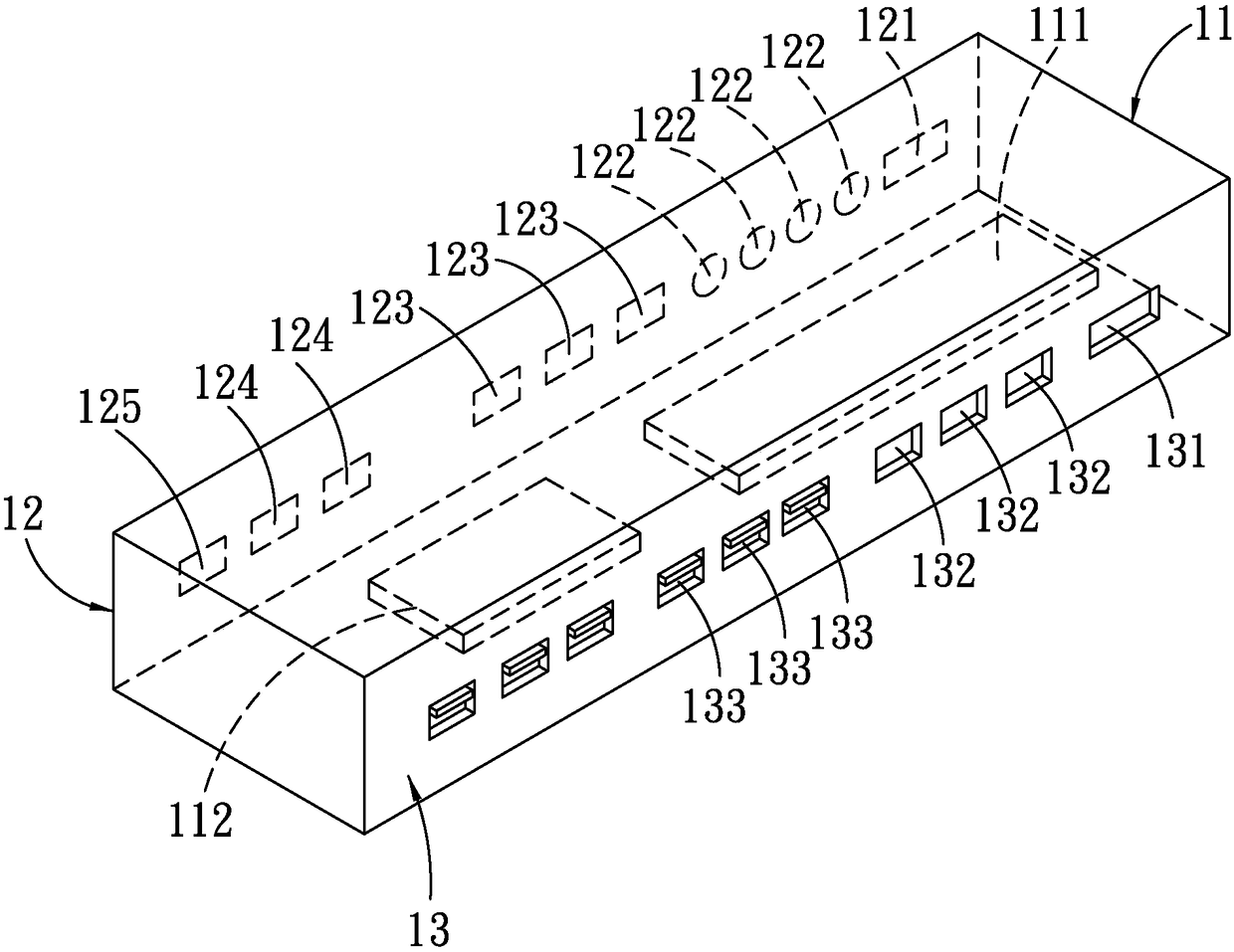
[0033] First, see figure 1 As shown, it is a structural schematic diagra...


PUM


Abstract

The invention relates to an orbit controlling ware applied to automation line's and an application method thereof. The orbit controlling ware is mainly applied to in various automation line's equipment to detect whether the production line in each workstation operation process appears unusually, and convey signals to a master control. The orbit controlling ware contains at least: a controller body, an entry end and an exit end. The controller body is internally provided with a main control substrate and a local lan concentrator for receiving and sending the signal, a side of the controller body is located at the entry end, and is provided with an upper signal input port, a plural photo sensor, a plural inductor interface, a compound digital circuit machine control interface and a plural communication interface, in order to send the signal to a controller body when unusual situation which is detected takes place; another side of the controller body is located at the exit end, and is provided with a next signal output port, a compound digital circuit machine control interface and a plural communication interface, in order to send the signal to the controller body when unusual situation which is detected takes place.

Description

technical field [0001] The present invention relates to a track controller technology for an automated production line, especially a track controller that can replace the existing track controller so that the interfaces are unified, so that the tracks of different equipment can be integrated together and transmit signals through a local area network to obtain the best results. Real-time working status and track controller for the fastest processing and its usage method. Background technique [0002] Automated production lines are already a common production method in automated factories today. Through automated production lines, each workstation can complete the operation process of each station one by one in an orderly manner, making production more efficient and reducing the risk of personnel directly operating workstations. [0003] However, in today's automated factories, each working machine operates independently, and each working machine has a different track controll...

Claims


Application Information

Patent Timeline
Patent Type & Authority Applications(China)
IPC IPC(8): G05B19/418
CPCG05B19/41875G05B2219/34465Y02P90/02
Inventor 杨娜陈涛王哲王向光岳朝贤
Owner 昆山亚伯兰软件科技有限公司
Learn More