
Power transformer partial discharge positioning method by means of ultrasonic reversal

A technology for power transformers and partial discharge, which is applied in the direction of using acoustic measurement for testing and testing dielectric strength, etc., which can solve problems such as waste of manpower and financial resources, difficult maintenance of power transformers, and waste of time

Active Publication Date: 2018-06-12
YUNNAN POWER GRID CO LTD KUNMING POWER SUPPLY BUREAU
View PDF7 Cites 6 Cited by
  • Summary
  • Abstract
  • Description
  • Claims
  • Application Information

AI Technical Summary

Problems solved by technology

However, due to the influence of the manufacturing process and long-term operation under different operating conditions, power transformers often have insulation defects in local areas. It will develop rapidly and produce partial discharge phenomenon, which will eventually lead to the failure of the power transformer insulation, thus making the maintenance of the power transformer more difficult, or even scrapped directly, resulting in a lot of waste of manpower and financial resources
In addition, due to the complex structure of the power transformer, if the location of the partial discharge of the power transformer cannot be known in advance, a lot of time will be wasted during the maintenance of the voltage transformer to locate the location of the partial discharge, thereby greatly prolonging the maintenance period and reducing the reliability of power supply
[0004] There are relatively mature partial discharge localization methods for power transformers, such as (1) the phase-controlled ultrasonic localization method and system for partial discharge of transformers disclosed in the patent application document with application number 200910175252.7, which uses phase-controlled The ultrasonic sensor receives the ultrasonic broadband signal from the partial discharge source, and then applies the broadband focusing algorithm, the narrowband direction finding algorithm and the crossover algorithm to process the received ultrasonic broadband signal to determine the specific location of the partial discharge. Since this method requires multiple measurements using different (2) The positioning method and device for transformer partial discharge ultrasonic source reconstruction disclosed in the patent application document with the application number of 201310060568.8 provides a time-reversal technology combined with transformer propagation The model calculates the position of the partial discharge source and the method of estimating the discharge volume, calculates the inversion sound field from the recorded sound pressure signal, realizes the aggregation of the sound field and the reconstruction of the sound source, and then determines the position of the discharge point and estimates the discharge according to the position and intensity of the focused sound field However, this method needs to accurately obtain the propagation model of the power transformer. Due to the complex structure of the power transformer, it is difficult to accurately establish the propagation model of the power transformer. Therefore, this method is difficult to accurately locate the location of the partial discharge source of the power transformer. At the same time , for different power transformers, the propagation models are also very different, this method lacks good generality

Method used


Image

  • Power transformer partial discharge positioning method by means of ultrasonic reversal
  • Power transformer partial discharge positioning method by means of ultrasonic reversal
  • Power transformer partial discharge positioning method by means of ultrasonic reversal

Examples


Embodiment 1

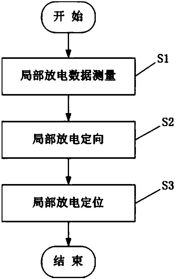
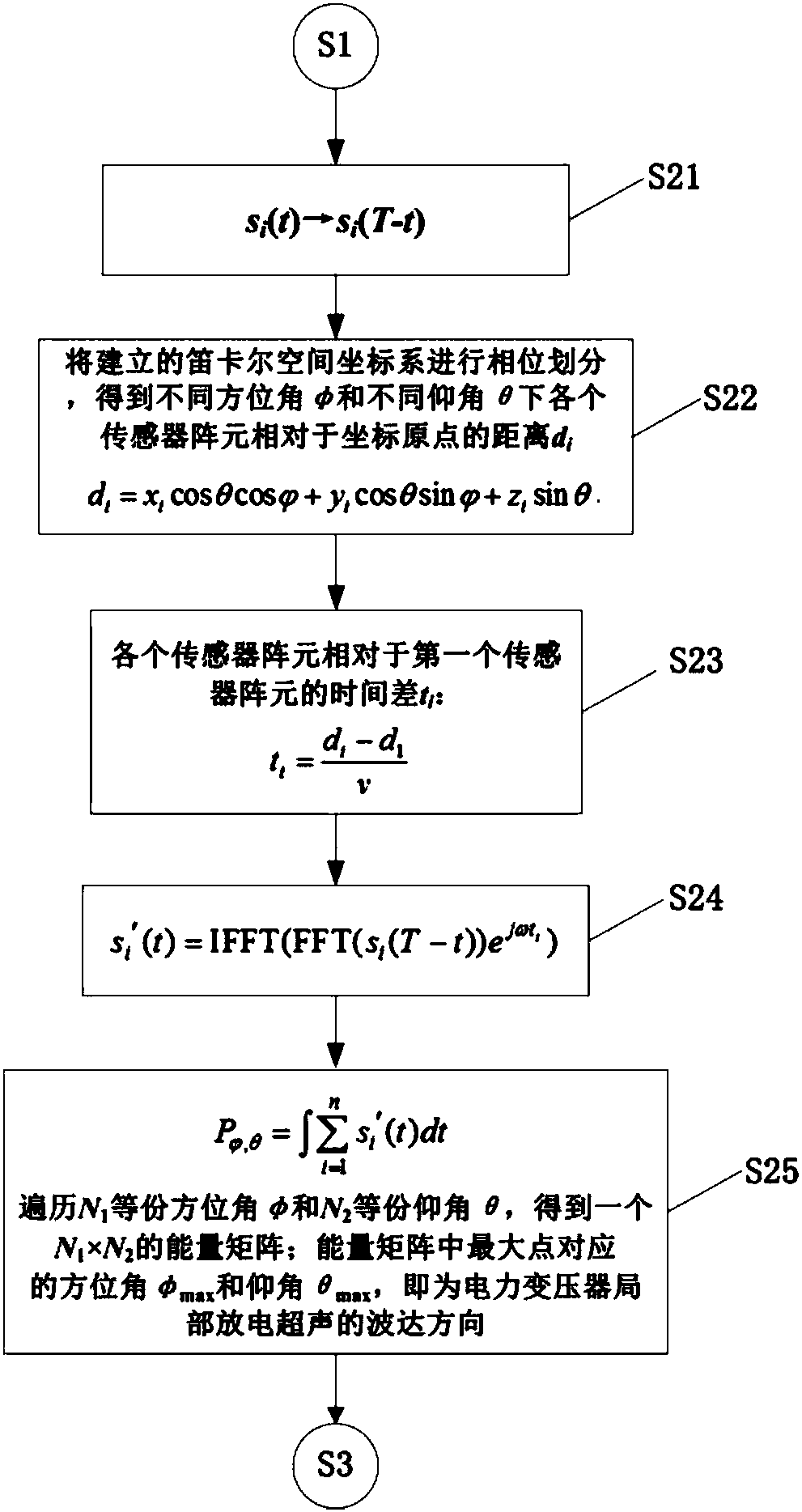
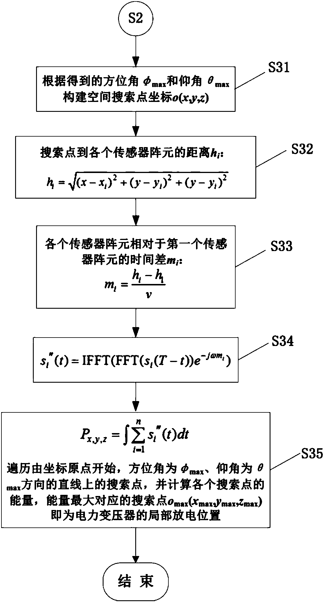
[0053] The physical size of the power transformer in this embodiment is 4m×4m×4m, and the partial discharge point is located at (1m, 1m, 2m). The local electrical positioning process of the power transformer using ultrasonic inversion is as follows: Figure 1 to Figure 3 shown, including the following steps:

[0054] S1. Partial discharge data measurement

[0055] The ultrasonic sensor array used in this embodiment is a 4×4 matrix composed of 16 sensors, and the distance between two adjacent ultrasonic sensors is 5mm. At the center of the surface, detect the ultrasonic signal s generated when the partial discharge of the power transformer occurs i (t), taking the geometric center of the ultrasonic sensor array as the origin, establish a Cartesian space coordinate system, and obtain the spatial position P of each sensor of the ultrasonic sensor array i (x i ,y i ,z i ), where i is the serial number of the sensor element in the ultrasonic sensor array, i is 1-16, t detectio...

Embodiment 2

[0084] The physical size of the power transformer in this embodiment is 4m×4m×4m, and the partial discharge point is located at (-1m, -0.5m, 1m). The local electrical positioning process of the power transformer using ultrasonic inversion is as follows: Figure 1 to Figure 3 shown, including the following steps:

[0085] S1. Partial discharge data measurement

[0086] The ultrasonic sensor array used in this embodiment is a 4×4 matrix composed of 16 sensors, and the distance between two adjacent ultrasonic sensors is 5mm. At the center of the surface, detect the ultrasonic signal s generated when the partial discharge of the power transformer occurs i (t), taking the geometric center of the ultrasonic sensor array as the origin, establish a Cartesian space coordinate system, and obtain the spatial position P of each sensor of the ultrasonic sensor array i (x i ,y i ,z i ), where i is the serial number of the sensor element in the ultrasonic sensor array, i is 1-16, t dete...


PUM


Abstract

The invention discloses a power transformer partial discharge positioning method by means of time reversal. The method comprises the steps of performing time reversal processing on measured power transformer partial discharge data, then, determining the power transformer partial discharge ultrasonic arrival direction according to time reversal ultrasonic signals, and then, determining the power transformer partial discharge position by searching in the partial discharge ultrasonic arrival direction. Accordingly, the search range can be greatly reduced, the time needed by searching the power transformer partial discharge position is greatly shortened, and the measuring efficiency and positioning precision of the power transformer partial discharge position can be improved.

Description

technical field [0001] The invention belongs to the technical field of electrical communication diagnosis, and relates to a partial discharge diagnosis technology in the operation of a power transformer, in particular to a method for local electrical positioning of a power transformer using ultrasonic inversion. Background technique [0002] A power transformer is a device used to change an AC voltage (current) of a certain value into another voltage (current) with the same frequency or several different values. It is an important part of ensuring the normal and reliable operation of the power system. [0003] With the development of the economy and the improvement of people's living standards, the power consumption continues to increase, requiring a large number of power transformers to be put into the operation of the power system. However, due to the influence of the manufacturing process and long-term operation under different operating conditions, power transformers oft...

Claims


Application Information

Patent Timeline
IPC IPC(8): G01R31/12
CPCG01R31/1209
Inventor 赵荣普赵威王欣万子逸杨进韦瑞峰陈永琴胡昌斌陈井锐李梦滔张国志吴辰阳陈欣段永生周涛
Owner YUNNAN POWER GRID CO LTD KUNMING POWER SUPPLY BUREAU
Learn More