
Laser line projection device

A laser line casting and laser technology, which is applied in the line casting machine field, can solve problems such as troublesome operation, construction impact, and trouble, and achieve the effect of avoiding manual positioning, convenient positioning, and accurate positioning

Pending Publication Date: 2018-06-12
遵义顶精机电工程有限责任公司
View PDF0 Cites 4 Cited by
  • Summary
  • Abstract
  • Description
  • Claims
  • Application Information

AI Technical Summary

Problems solved by technology

[0002] In the existing technology, in the fields of construction and decoration, it is often necessary to perform positioning and leveling during the process of the suspended ceiling and ceiling shape of the house, the installation of various equipment on the roof and the decoration of the ceiling, and the existing method is Leveling by manual measurement and positioning or perforated paper positioning, this positioning method is cumbersome to operate, and the positioning will have visual deviation and inaccuracy, which will affect the subsequent construction and affect the appearance of the ceiling. For example, the installation of electrical equipment on the top, Such as the installation of fresh air equipment for central air-conditioning, these decorations need to be perfectly integrated with the decoration, so the top hoisting requires high precision. During the installation process of traditional central air-conditioning, the internal unit of the air conditioner needs to be hoisted on the top surface through four poles. Between the wall and the ceiling, the commonly used method is to use expansion bolts to drive the four poles to the top wall, and the positioning of the expansion screws will bring inconvenience to the construction personnel: the installation of the expansion screws needs to be installed on the top wall first. Carry out positioning, and then drill holes. However, in the process of positioning, construction personnel need to make a rough position judgment first, and then need to climb to a high place through a ladder or scaffolding to measure the size with measuring tools such as a tape measure. However, because it is a rectangular positioning measurement The operation is very cumbersome and imprecise, and it is easy to cause visual errors

Method used


Image

  • Laser line projection device
  • Laser line projection device
  • Laser line projection device

Examples


Embodiment Construction

[0034] The principles and features of the present invention are described below in conjunction with the accompanying drawings, and the examples given are only used to explain the present invention, and are not intended to limit the scope of the present invention.

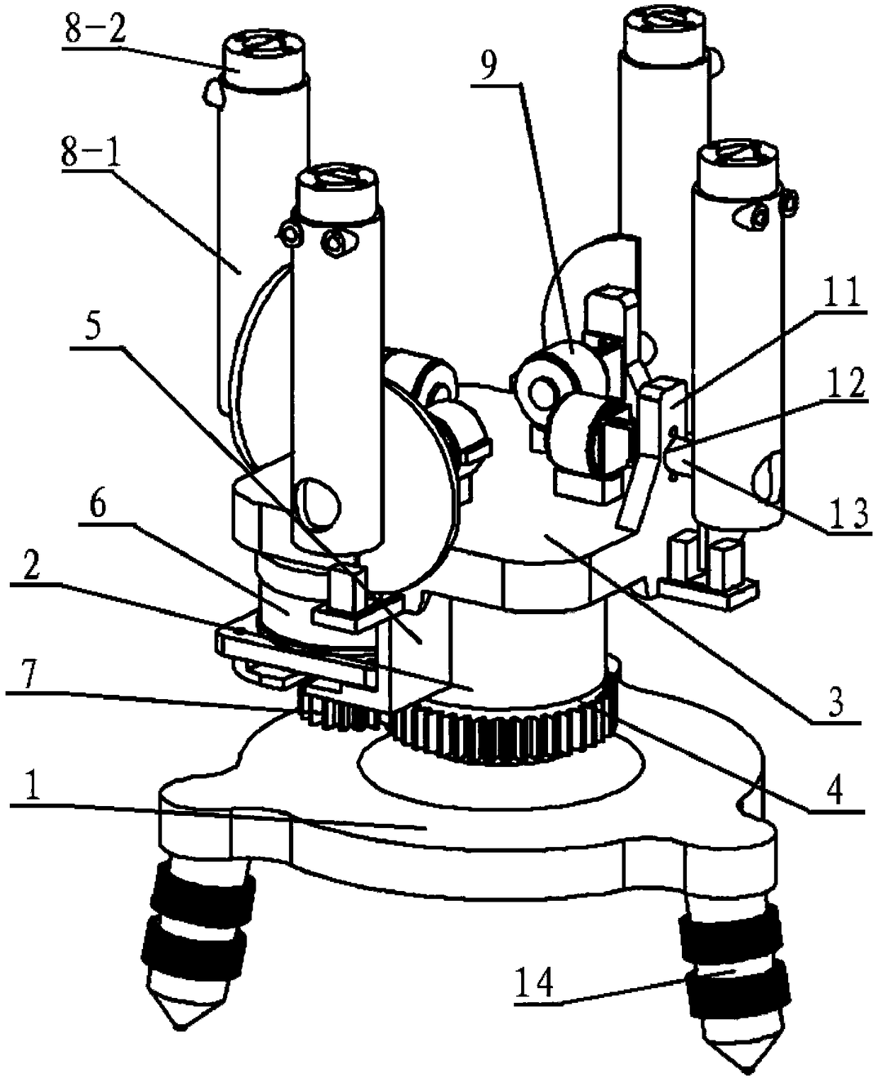
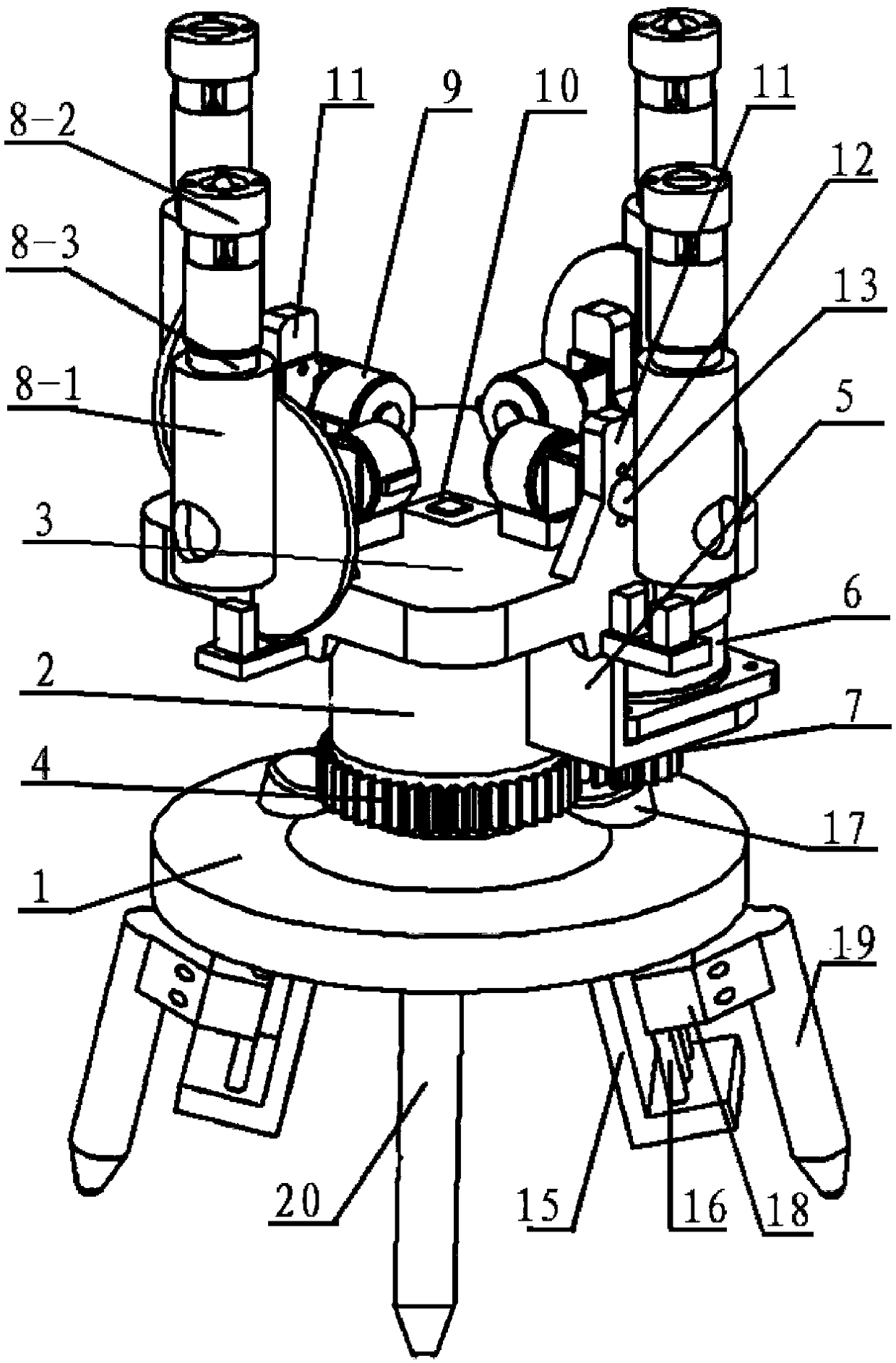
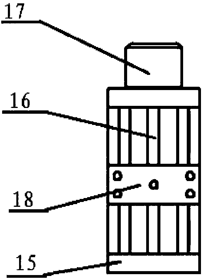
[0035] Such as figure 1 As shown, the first embodiment of the present invention includes a base 1, on which a base 2 is arranged, and the bottom of the base 2 is fixed on the upper surface of the base 1, and the base The top of the column 2 is provided with a rotating platform 3 that can rotate horizontally and axially, and the base column 2 is sleeved with a ring gear 4, the axis of the ring gear 4 coincides with the axis of rotation of the rotating platform 3; The platform 3 is provided with a rotating motor fixing seat 5, and the rotating motor fixing seat 5 is fixed with a rotating motor 6, and the output shaft of the rotating motor 6 is connected with a rotating gear 7, and the rotating gear 7 is connected to t...


PUM


Abstract

The invention relates to a laser line projection device which comprises a base table. A base column is arranged on the base table, the bottom of the base column is fixed onto the upper surface of thebase table, a rotary platform capable of horizontally and axially rotating is arranged at the top of the base column, and an annular gear sleeves the base column. A rotary motor is fixedly arranged onthe rotary platform, and a rotary gear is arranged on an output shaft of the rotary motor in a transmission connection manner and engaged with the annular gear. Four laser modules are arranged on therotary platform, are fixed onto the rotary platform by the aid of deflection motors and can be driven by the deflection motors to deflect in the vertical direction. The laser line projection device has the advantages that rectangular projection with different sizes and in different shapes can be projected at indoor tops and on wall surfaces as needed, mounting and positioning at the indoor tops and on the wall surfaces can be facilitated, manual positioning by mounting personnel can be omitted, and positioning is more convenient and accurate.

Description

technical field [0001] The invention relates to the technical field of wire throwing instruments, in particular to a laser wire throwing device. Background technique [0002] In the existing technology, in the fields of construction and decoration, it is often necessary to perform positioning and leveling during the process of the suspended ceiling and ceiling shape of the house, the installation of various equipment on the roof and the decoration of the ceiling, and the existing method is Leveling by manual measurement and positioning or perforated paper positioning, this positioning method is cumbersome to operate, and the positioning will have visual deviation and inaccuracy, which will affect the subsequent construction and affect the appearance of the ceiling. For example, the installation of electrical equipment on the top, Such as the installation of fresh air equipment for central air-conditioning, these decorations need to be perfectly integrated with the decoration...

Claims


Application Information

Patent Timeline
IPC IPC(8): G01C9/00
CPCG01C9/00
Inventor 柯学敬志渝韦刚杨培伟巫潘
Owner 遵义顶精机电工程有限责任公司
Learn More