A buffer relief valve

A technology of overflow valve and buffer valve, which is applied in the direction of fluid pressure actuators, servo motor components, mechanical equipment, etc., can solve the problems of unsatisfactory buffer time control, shortened buffer time, high pressure sensitivity, etc., to achieve constant flow, The effect of stable buffer time and good working pressure requirements

Active Publication Date: 2019-07-23
KEVINS FLUID CONTROL (JIANGSU) CO LTD
View PDF12 Cites 0 Cited by
  • Summary
  • Abstract
  • Description
  • Claims
  • Application Information

AI Technical Summary

Problems solved by technology

[0005] (3) It uses the damping hole to control the buffering time. The flow through the damping hole is not constant, and the sensitivity to pressure is high. When the pressure is low, the buffering time is longer, and when the pressure is high, the buffering time is shortened. The control of the buffering time Not ideal, in a large fluctuation range

Method used


Image

  • A buffer relief valve
  • A buffer relief valve

Examples


Embodiment Construction

[0023] In order to make the technical solutions and advantages of the present invention clearer, the exemplary embodiments of the present invention will be further described in detail below in conjunction with the accompanying drawings. Apparently, the described embodiments are only a part of the embodiments of the present invention, and are not exhaustive of all the embodiments. And in the case of no conflict, the embodiments and the features in the embodiments of the present invention can be combined with each other.

[0024] During the invention process, the inventor noticed that the existing threaded cartridge adjustable buffer overflow valve has problems such as complex structure, limited buffer impact pressure and unstable buffer control.

[0025] In view of the above shortcomings, an embodiment of the present invention proposes a buffer overflow valve, which will be described below.

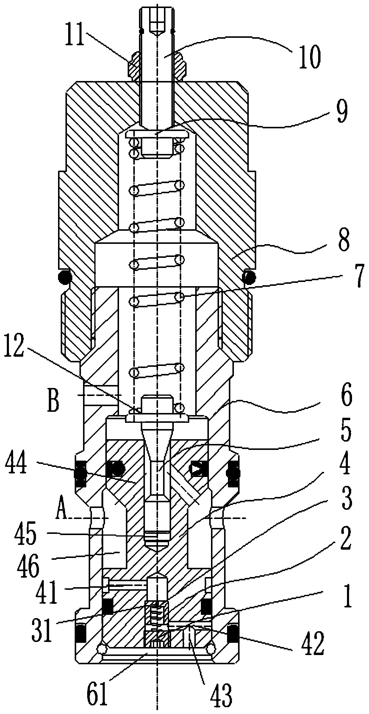
[0026] figure 1 One embodiment of a surge relief valve of the present invention is s...


PUM


Abstract

The invention provides a buffer overflow valve which comprises a valve body, a buffer flow stabilization assembly, a main valve element and a swivel nut. The valve body is provided with an oil port Aand an oil port B, the buffer flow stabilization assembly is arranged in the valve body and divides the oil port A and the oil port B, a main valve element cavity communicated with the oil port A is arranged in the buffer flow stabilization assembly, a buffer cavity is formed by the buffer flow stabilization assembly and the valve body, the main valve element is connected to the main valve elementcavity and is connected to a valve opening of the main valve element cavity in a pressed manner, the swivel nut is connected to the other end of the valve body and is internally provided with a pressure adjusting mechanism, and the pressure adjusting mechanism is connected with one end of the main valve element to control opening and closing of the main valve element. By means of the buffer overflow valve, the impact pressure can be effectively buffered, the buffer time is more stable, the structure is simpler, and machining is more convenient.

Description

technical field [0001] The invention relates to the technical field of valves, in particular to a buffer overflow valve. Background technique [0002] In the modern mechanical equipment slewing device, a large number of buffer function hydraulic circuits are used, such as excavator slewing device, crane slewing device, aerial vehicle slewing device, manipulator slewing device and agricultural and forestry machinery slewing device, among which the buffer overflow valve is the As the key hydraulic components of such systems, the performance of the buffer relief valve directly affects the performance of the main engine. The existing buffer overflow valve is divided into plate type buffer overflow valve and cartridge type buffer overflow valve according to the connection mode. In order to reduce the installation space and improve system reliability in the system, the cartridge type buffer overflow valve is generally used. valve. For example, the patent with the announcement nu...

Claims


Application Information

Patent Timeline
Patent Type & Authority Patents(China)
IPC IPC(8): F15B13/02
CPCF15B13/023
Inventor 邵立坤
Owner KEVINS FLUID CONTROL (JIANGSU) CO LTD
Why Eureka
Try Eureka