


Quick Research
Generate reliable direction feasibility study reports for your R&D in just a few steps.

Technical Q&A
Discover and master advanced knowledge NOW. Basics, ideas, possibilities, all at once.

Find Solutions
As an expert in R&D theories, this can generate solutions to your technical problems instantly.

Evaluate Feasibility
Analyze your overall solution with one click, know your potential R&D risks in advance.

Monitor Landscape
Get weekly tech updates, stay abreast of the latest tech innovations and key insights.
Travel control method and travel control device
A control method and driving control technology, applied in control devices, traffic control systems, non-electric variable control, etc., can solve problems such as precision detection
- Summary
- Abstract
- Description
- Claims
- Application Information
AI Technical Summary
Problems solved by technology
Method used
Image

Examples
no. 1 approach 》
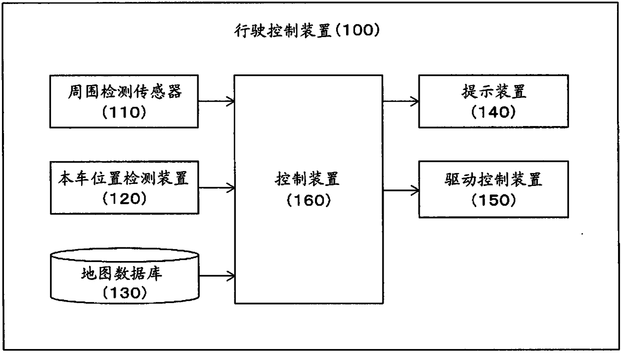
[0033] figure 1 It is a figure which shows the structure of the travel control apparatus 100 of this embodiment. Such as figure 1 As shown, the travel control device 100 of this embodiment includes: a surrounding detection sensor 110 , a vehicle position detection device 120 , a map database 130 , a presentation device 140 , a drive control device 150 , and a control device 160 . In order to receive and send information to each other, these devices are connected by in-vehicle LAN in addition to CAN (Controller Area Network).
[0034] The surrounding detection sensor 110 detects obstacles (other vehicles, etc.) and road markings (lane markings, curbs, etc.) existing around the own vehicle. As the surrounding detection sensor 110 , for example, a front camera that captures the front of the own vehicle, a rear camera that captures the rear of the host vehicle, a side camera that captures the side of the host vehicle, etc. can be used. In addition, as the surrounding detection ...
no. 2 approach 》
[0075] Next, a travel control device according to a second embodiment will be described. The travel control device 100 of the second embodiment has the same configuration as the travel control device 100 of the first embodiment, and is the same as the first embodiment except that it operates as described below.
[0076] The surrounding vehicle allocation function of the control device 160 in the second embodiment predicts the lanes of the surrounding vehicles based on the direction of travel of each lane in the road on which the surrounding vehicles are traveling and the lighting status of the blinkers of the surrounding vehicles, and arranges the surrounding vehicles. within the predicted lane.
[0077] here, Figure 8 is a diagram illustrating a scene where the own vehicle enters a T-junction. exist Figure 8In the illustrated example, the surrounding vehicle A is actually traveling on the lane A, but the surrounding vehicle A is detected between the lanes A and B due to ...
no. 3 approach 》
[0097] Next, a travel control device according to a third embodiment will be described. The travel control device 100 of the third embodiment has the same configuration as the travel control device 100 of the first embodiment, and is the same as the first embodiment except that it operates as described below.
[0098] In the third embodiment, the surrounding vehicle arrangement function of the control device 160 determines the positions of the host vehicle and surrounding vehicles on the map based on road indications and road shapes (including road curves). In addition, road indications are stop lines, signs, signal machines, fire hydrants, etc., which can be fixed on the road surface or its vicinity, and can be used as indications. In addition, the road shape is a road shape such as a curve.
[0099]The surrounding vehicle allocation function detects road indications and road shapes based on detection results of a camera or a laser rangefinder constituting the surrounding de...
PUM
 Abstract
Description
Claims
Application Information
 - R&D Engineer
- R&D Manager
- IP Professional
- Industry Leading Data Capabilities
- Powerful AI technology
- Patent DNA Extraction
Browse by: Latest US Patents, China's latest patents, Technical Efficacy Thesaurus, Application Domain, Technology Topic, Popular Technical Reports.
© 2024 PatSnap. All rights reserved.Legal|Privacy policy|Modern Slavery Act Transparency Statement|Sitemap|About US| Contact US: help@patsnap.com