
Backlight module and display device

A backlight module, backlight display technology, applied in the direction of light guide, optics, optical components, etc., to achieve the effect of improving the light mixing distance

Inactive Publication Date: 2018-06-08
XIAMEN TIANMA MICRO ELECTRONICS
View PDF10 Cites 24 Cited by
  • Summary
  • Abstract
  • Description
  • Claims
  • Application Information

AI Technical Summary

Problems solved by technology

[0004] Embodiments of the present invention provide a backlight module and a display device to solve the problem of firefly effects under narrow borders existing in the prior art

Method used


Image

  • Backlight module and display device
  • Backlight module and display device
  • Backlight module and display device

Examples


Embodiment Construction

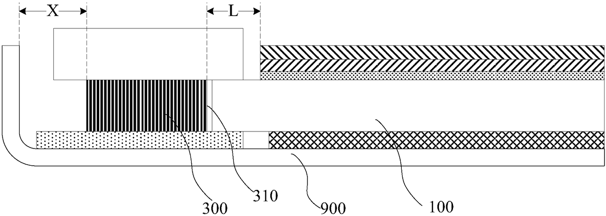
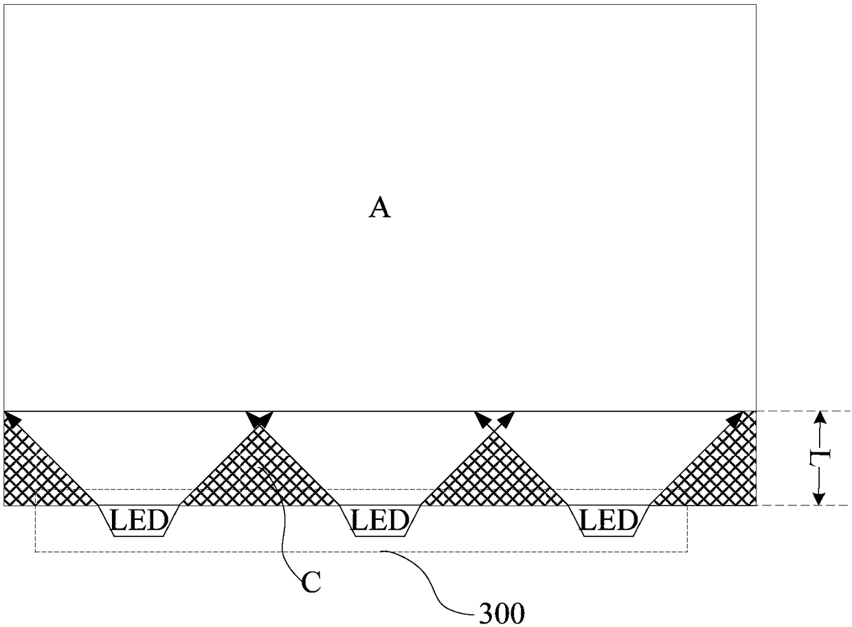
[0041] At present, in the backlight module, such as figure 1 As shown, the side-type backlight 300 is incident on the side of the light guide plate 100 , and its light emitting surface 310 faces the light guide plate 100 . Since the dimension X between the side-type backlight 300 and the outermost side of the backplane 900 involves the requirements of the FPC trace width and the reliability adhesive area, the dimension X of this part has a limit requirement and cannot be compressed. When the frame needs to be narrowed, the light mixing distance L will be compressed, that is, the distance from the light emitting surface 310 of the side-type backlight 300 to the backlight display area A of the light guide plate 100 . Such as figure 2 As shown, when the light mixing distance is small, the dark area C between the LED lights in the side-lit backlight 300 will stand out, forming a firefly effect.

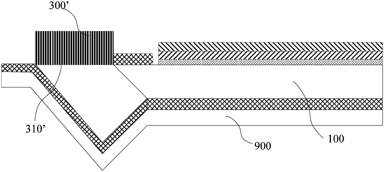
[0042] Similarly, if image 3 As shown, in the backlight module, the direct-type ...


PUM


Abstract

The invention discloses a backlight module and a display device. Light-emitting surfaces of lateral emitting type backlight sources are changed to deviate from a backlight display region from an existing manner of facing the backlight display region, and a light guide part is arranged at an edge of a non-display region of a light guide plate; light which is transmitted in the light guide part andis emitted by the lateral emitting type backlight sources is reflected to the light guide plate through a reflecting part which is arranged on a first surface, opposite to a light emitting surface, ofthe light guide part, so that a light guide function of the backlight module is realized. Compared with an existing backlight module structure, on the basis of taking a distance between a side face facing the backlight display region of the existing lateral emitting type backlight sources and a boundary, close to the lateral emitting type backlight sources, of the backlight display region as a light mixing distance under the condition of ensuring a narrow edge frame structure design, the following light mixing distances are increased: a maximum distance between the light emitting surfaces ofthe two lateral emitting type backlight sources and the first surface, and the length of the lateral emitting type backlight sources in the direction vertical to the light emitting surfaces; the glowworm effect is easily improved under a narrow edge frame.

Description

technical field [0001] The invention relates to the field of display technology, in particular to a backlight module and a display device. Background technique [0002] At present, backlight modules applied to liquid crystal display panels are usually provided with light-emitting diode (light-emitting diode, LED) light strips on the side of the light guide plate. The internal total reflection is carried out, and the dots set on the light-emitting surface of the light guide plate destroy the total reflection of the light inside the light guide plate, so that the light is uniformly emitted from the light-emitting surface of the light guide plate, and the point light source is converted into a surface light source. [0003] Since the LED light is incident on the side of the light guide plate, in order to ensure uniform brightness inside the light guide plate, the light-emitting surface is usually set at a position behind the set length from the light-incoming surface of the lig...

Claims


Application Information

Patent Timeline
Patent Type & Authority Applications(China)
IPC IPC(8): G02F1/13357G02B6/00
CPCG02B6/0031G02F1/133615
Inventor 洪耀武艾有俊张洁周伟张中杰
Owner XIAMEN TIANMA MICRO ELECTRONICS
Learn More