Working method of temperature control industrial thermostat for hydraulic bypass with spherical pressure relief valves

A working method and technology of pressure relief valve, applied in the direction of temperature control, mechanical equipment, servo meter circuit, etc., can solve the problems of easy damage of radiators, scrapping, unbalanced flow, exceeding the radiator, etc., to prolong the service life and guarantee The effect of stable operation and energy saving

Inactive Publication Date: 2018-06-08
江苏金荣森制冷科技有限公司
View PDF4 Cites 0 Cited by
  • Summary
  • Abstract
  • Description
  • Claims
  • Application Information

AI Technical Summary

Problems solved by technology

It has a small liquid storage capacity and no buffer. In the case of large temperature difference, low temperature environment, unbalanced flow, liquid with a certain viscosity, and fluid with impact force, the pressure inside the heat dissipation channel of the radiator will also increase. , especially in the case of impact force and relatively high viscosity fluid, due to the resistance of the fluid inside the channel, the fluid cannot quickly pass through the inside of the radiator channel, so that the pressure increases, exceeding the maximum operating pressure of the radiator, and the radiator is very Easily damaged and scrapped

Method used


Image

  • Working method of temperature control industrial thermostat for hydraulic bypass with spherical pressure relief valves
  • Working method of temperature control industrial thermostat for hydraulic bypass with spherical pressure relief valves
  • Working method of temperature control industrial thermostat for hydraulic bypass with spherical pressure relief valves

Examples


Embodiment 1

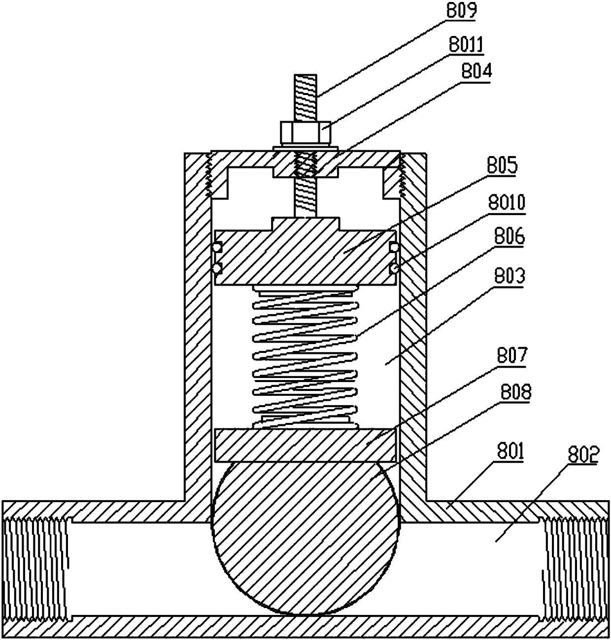
[0078] Example 1. When the liquid flows from left to right and the main hydraulic circuit is blocked, the pressure at the left end of the ball pressure relief valve is greater than the pressure at the right end, because the pressure in the fluid channel on the left side of the ball is greater than the pressure in the fluid channel on the right side of the ball Pressure, the fluid pushes the ball upwards, the bottom of the ball forms a space for the fluid to move, the fluid moves from left to right in the fluid channel, so as to achieve the purpose of pressure relief, until the pressure on the left and right sides of the ball is equal, the ball returns to its original position position, the main hydraulic circuit returns unobstructed.

Embodiment 2

[0079] Example 2. When the liquid flows from left to right and the hydraulic main road is blocked, the pressure at the right end of the ball relief valve is greater than the pressure at the left end, because the pressure in the fluid channel on the right side of the ball is greater than the pressure in the fluid channel on the left side of the ball Pressure, the fluid pushes the ball upwards, the bottom of the ball forms a space for the fluid to move, the fluid moves from right to left in the fluid channel, so as to achieve the purpose of pressure relief, until the pressure on the left and right sides of the ball is equal, the ball returns to its original position position, the main hydraulic circuit returns unobstructed.


PUM


Abstract

The invention relates to a temperature control industrial thermostat for hydraulic bypass with spherical pressure relief valves. The industrial thermostat is characterized in that step one, equipmentheating source (900) and the industrial thermostat are connected; step two, when the thermostat is started, firstly an oil storage tank temperature sensor (908) or a hydraulic oil delivery pipeline temperature sensor (103) detects the temperature of liquid, a heating mode is turned on when the temperature is lower than 35 DEG C, and a cooling mode is turned on when the temperature is higher than 60 DEG C. The industrial thermostat has the advantage of high reliability and is not easy to damage, and stable operation of a system is ensured.

Description

technical field [0001] The invention relates to a working method of a temperature-controlling industrial constant temperature machine with a hydraulic bypass of a ball-type pressure relief valve. Background technique [0002] As we all know, the optimal oil temperature of the hydraulic system is between 35 and 55 degrees Celsius. Once the temperature rises above 60 degrees Celsius, the system working efficiency of the hydraulic system will be greatly reduced, and equipment failures will continue to occur, resulting in serious equipment stability. decline, the normal operation of machinery and equipment cannot be guaranteed. Especially in the midsummer season, the oil temperature is too high, and even the machinery and equipment are often shut down. In winter, especially in severe cold areas, the oil temperature is low, the oil temperature inside the hydraulic system is low, the viscosity is high, the fluidity is poor, and the work efficiency is also poor. Forcibly operating...

Claims


Application Information

Patent Timeline
Patent Type & Authority Applications(China)
IPC IPC(8): F15B21/04G05D23/20
CPCF15B21/042F15B2211/62G05D23/20
Inventor 黄晓军
Owner 江苏金荣森制冷科技有限公司
Why Eureka
Try Eureka