Sucker rod centering device capable of being conveniently dismounted and mounted

A technology for easy disassembly and assembly of sucker rods, applied in the direction of drill pipes, earthwork drilling, drilling equipment, etc., can solve the problems of high maintenance costs, cumbersome operations, high labor intensity, etc., and achieve extended service life, simple design structure, The effect of improving the overall strength

Pending Publication Date: 2018-06-08
QINGDAO OUSHENG LIGHTING CO LTD
View PDF12 Cites 3 Cited by
  • Summary
  • Abstract
  • Description
  • Claims
  • Application Information

AI Technical Summary

Problems solved by technology

Complicated operation, high labor intensity and high maintenance cost
Although there is a slip-type butt joint centralizer, due to its unreasonable structural design, the centralization effect is poor when it slides on the sucker rod during use, and it is easy to be damaged and fall off. The resulting debris is easy to get stuck in the pump, which increases the maintenance cost. restricted

Method used


Image

  • Sucker rod centering device capable of being conveniently dismounted and mounted
  • Sucker rod centering device capable of being conveniently dismounted and mounted
  • Sucker rod centering device capable of being conveniently dismounted and mounted

Examples


Embodiment 1

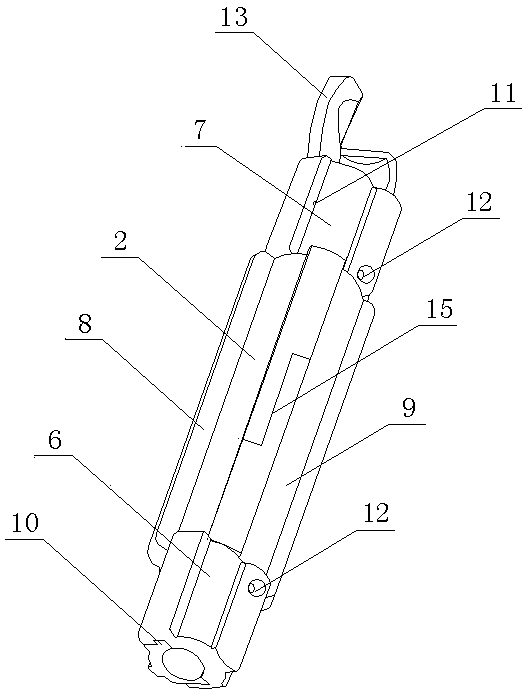
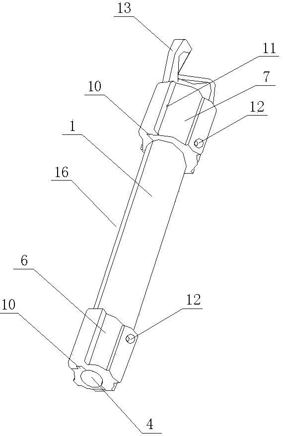
[0016] The convenient detachable sucker rod centralizer of the present invention is composed of a rod frame 1 and a wing barrel 2 . The rod frame 1 is a cylindrical pipe section formed by longitudinal insertion of two semicircular tile tubes 3, the inside of which is the sucker rod channel 4, the middle part is the frame rod 5 of the wing tube 2 with reduced diameter, and the lower end is The wing tube seat platform 6 and the upper end of the expanded diameter are the wing tube limiting pressure table 7 of the expanded diameter. The wing tube 2 is composed of two relatively snap-connected tile tubes 9 with longitudinal fins 8 on the outer wall, and the wing tube 2 is sleeved on the sleeve groove 16 in the middle section of the rod section of the rod frame 1 .

Embodiment 2

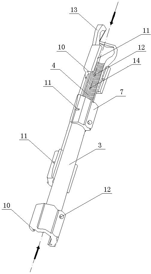
[0018] The convenient detachable sucker rod centralizer of the present invention is composed of a rod frame 1 and a wing barrel 2 . The rod frame 1 is a cylindrical pipe section formed by longitudinal insertion of two semicircular tile cylinders 3 with textures 14 that increase the frictional force on the inner surface, and the inside of the cylinder is the sucker rod channel 4, The middle section is the support bar 5 of the wing tube 2 with reduced diameter, the lower end is the wing tube seat platform 6 with expanded diameter, and the upper end is the wing tube limit press platform 7 with expanded diameter. The outer periphery of rod frame 1 between 7 forms sleeve groove 16. Said wing barrel 2 is composed of two relatively snap-fit ​​tile barrels 9 with longitudinal fins 8 on the outer wall, and the wing barrel 2 is set on the fitting groove 16 . More than one longitudinal fin 8 is arranged on the outer periphery of the airfoil 2 , and the outer edge of each airfoil 8 protr...


PUM


Abstract

The invention provides a sucker rod centering device capable of being conveniently dismounted and mounted and belongs to the technical field of fastening members. The sucker rod centering device is composed of a rod frame and a wing barrel, wherein the rod frame is of a cylindrical pipe section formed by longitudinally inserting two pieces of semicircular slip barrels; a sucker rod channel is arranged in the barrel, the middle section is a frame rod of the diameter-reducing wing barrel, the lower end is a diameter-expanding wing barrel seat platform and the upper end of a diameter-expanding wing barrel limiting pressing platform; the wing barrel is composed of two pieces of slip barrels which are in relative clamping joint and a longitudinal wing sheet is arranged on an outer wall of eachslip barrel; the wing barrel sleeves a sleeve groove located at the middle section of the a cylindrical pipe section of the rod frame. According to the sucker rod centering device capable of being conveniently dismounted and mounted, provided by the invention, the whole mechanical strength of the centering device is effectively improved; a texture type surface at the inner side enables the installation to be firmer and the sucker rod centering device does not slip and does not fall off. A retracting and clamping joint structure is adopted, the design structure is simple and the installation isconvenient; a very good centering effect on a sucker rod is realized and a rod pipe can be prevented from being effectively eccentrically abraded, so that the service life of the sucker rod is prolonged and the reliability of a rod pumping well oil production system is improved.

Description

technical field [0001] The invention belongs to the technical field of fastening components, in particular to a sucker rod centralizer which is convenient for assembly and disassembly. Background technique [0002] Most of the oil wells in the oil field are produced by oil pumps, and the sucker rods of the oil pumps often wear eccentrically with the tubing in the wellbore, resulting in damage to components or equipment, resulting in failures or production accidents. In order to prevent eccentric wear of the sucker rod, the sucker rod is fitted with a centralizer with fins. Prior art centralizers typically have a vaned sleeve that fits over each oil recovery tube. Its disadvantage is that it is necessary to stop working and disconnect the sucker rods during assembly, and to assemble them one by one. The operation is cumbersome, the labor intensity is high, and the maintenance cost is high. Although there is a slip-type butt joint centralizer, due to its unreasonable struct...

Claims


Application Information

Patent Timeline
Patent Type & Authority Applications(China)
IPC IPC(8): E21B17/10
CPCE21B17/1071
Inventor 张广庆宋文强
Owner QINGDAO OUSHENG LIGHTING CO LTD
Why Eureka
Try Eureka