
Centrifugal slurry separator

A separator and centrifugal technology, applied in the field of centrifugal slurry separators, can solve the problems of inconvenient operation of the device, difficult separation operation, etc., and achieve the effects of convenient operation, good filtering and separation effect, and simple device structure.

Active Publication Date: 2018-06-08
枞阳县田园面业有限责任公司
View PDF7 Cites 0 Cited by
  • Summary
  • Abstract
  • Description
  • Claims
  • Application Information

AI Technical Summary

Problems solved by technology

[0003] The technical problem to be solved by the present invention is to overcome the defects of difficult separation operation and inconvenient operation of the device in the prior art, and provide a centrifugal slurry separator

Method used


Image

  • Centrifugal slurry separator

Examples


Embodiment Construction

[0011] In order to make the technical means, creative features, goals and effects achieved by the present invention easy to understand, the present invention will be further described below in conjunction with specific embodiments.

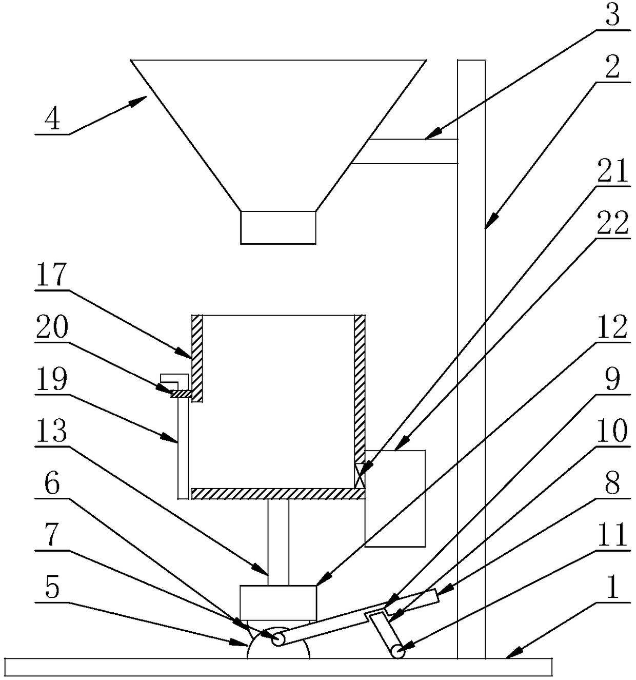
[0012] When using a centrifugal slurry separator in this embodiment, please refer to figure 1 , the present invention provides a technical solution: a centrifugal powder-slurry separator, including an operating table 1, a support rod 2 is fixedly connected to the top of the operating table 1 close to the right side, and the left side of the support rod 2 is close to the top A connecting rod 3 is fixedly connected, and the side of the connecting rod 3 away from the support rod 2 is fixedly connected with a material storage tank 4, and the operation table 1 is fixedly connected with a concave block 5, and the concave block 5 is movably connected to the convex through a pin shaft 7. block 6, and the pin shaft 7 is fixedly connected with the convex bl...


PUM


Abstract

The invention discloses a centrifugal slurry separator. The centrifugal slurry separator comprises an operating platform, wherein a support rod is fixedly connected to the part, near the right side, of the top of the operating platform, a connecting rod is fixedly connected to the part, near the top, of the left side of the support rod, and the operating platform is fixedly connected with a concave block; one end of a pin shaft penetrates through the front end surface of the concave block and extends to the outside of the concave block, a rotary shaft is fixedly connected to the top of the operating platform, and the top of a bump is fixedly connected with a first motor; the power output end of the first motor is fixedly connected with the bottom of a cylinder, a mobile plate is arranged at an opening in the left side of the cylinder, a filter screen is arranged at an opening in the right side of the cylinder, and a material storage tank is fixedly connected with the opening in the right side of the cylinder. The centrifugal slurry separator has the characteristics of convenient manual operation and good effects of separation and filtration, and is suitable for home use.

Description

technical field [0001] The invention relates to the technical field of mechanical production equipment, in particular to a centrifugal slurry separator. Background technique [0002] In daily life, the role of agricultural machinery is ubiquitous. Among them, the appearance of household potato crushers has brought many benefits to people's lives. After the potato is crushed, there will inevitably be some potato skins in the slurry. If it is processed Filtration treatment, the potato skin is processed to obtain a slurry, which can avoid the waste of raw materials. With the development of technology, people are often not satisfied with the preparation of the existing centrifugal slurry separator. On the basis of the conventional slurry separator, it is improved. The common centrifugal slurry separator will be too difficult to separate the potato skins mixed in it due to the state of the slurry when it is working, and it is generally The device is not suitable for household us...

Claims


Application Information

Patent Timeline
Patent Type & Authority Applications(China)
IPC IPC(8): B01D33/15
CPCB01D33/15
Inventor 汤晓业
Owner 枞阳县田园面业有限责任公司
Learn More