Wireless charging method and flexible terminal
A technology for wireless charging and wireless charging equipment, applied in electrical components, circuit devices, etc., can solve the problems of long charging time, limited size and number of charging coils, and slow charging speed
- Summary
- Abstract
- Description
- Claims
- Application Information
AI Technical Summary
Problems solved by technology
Method used
Image
Examples
no. 1 example
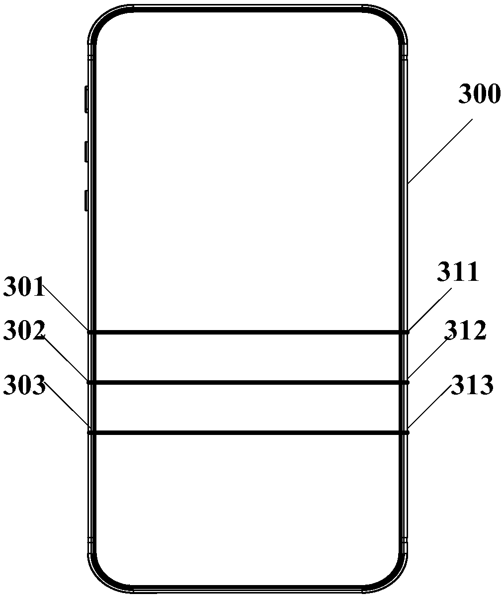
[0070] In order to solve the problem in the prior art that the charging current is limited due to the limited size and number of charging coils installed in the wireless charging terminal, which in turn leads to slow charging speed and long charging time, this embodiment provides a wireless charging method , this method is applied to a flexible terminal with at least two metal wires in the same direction embedded in the terminal; the specific wireless charging method can be found in Figure 5 as shown, Figure 5 The basic flow chart of the wireless charging method provided in this embodiment, the method includes:
[0071] S501. When charging is required, bend the flexible terminal into a charging form, wherein the charging form is to curl the flexible terminal into a closed loop along the extending direction of the metal wire, so that the metal wire is closed to form an input coil;
[0072] In this embodiment, when performing wireless charging, it is necessary to curl the fle...
no. 2 example
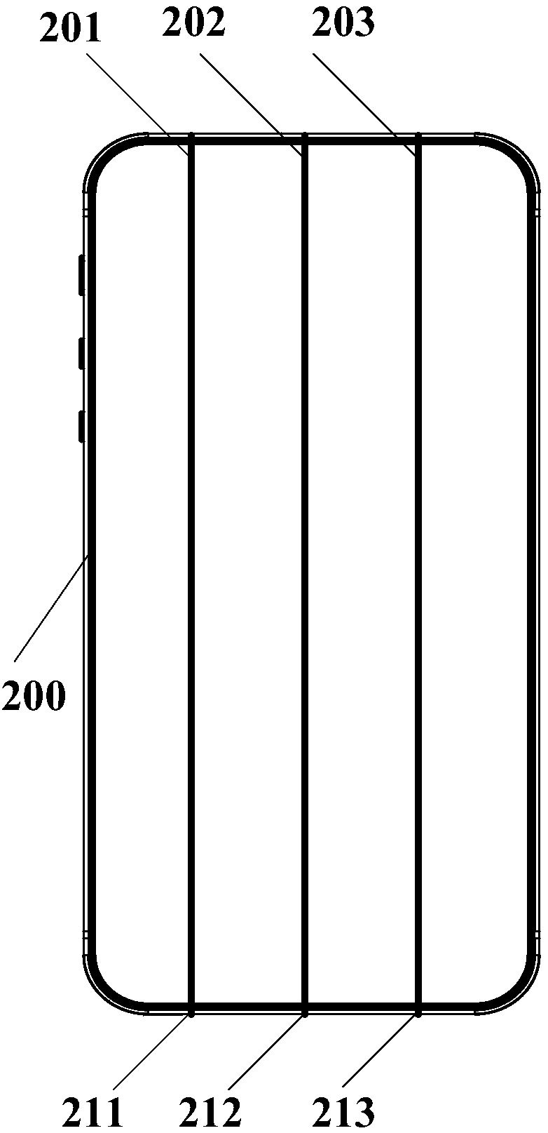
[0093] In order to better understand the present invention, this embodiment is described in conjunction with a more specific example: assuming that at least two metal wires along the length direction of the terminal are buried inside the flexible terminal, and the metal wires are parallel to the length direction; see Image 6 as shown, Image 6 It is a detailed flow chart of the wireless charging method provided by the second embodiment of the present invention, the wireless charging method includes:
[0094] S601. When charging is required, bend the flexible terminal into a charging form, wherein the charging form is to curl the flexible terminal into a closed loop along the length direction, so that the metal wire is closed to form an input coil;
[0095] In this embodiment, when performing wireless charging, the flexible terminal needs to be curled into a closed loop along the length direction of the terminal, so that the metal wires are closed to form an input coil.
[00...
example 1
[0111] In order to better understand the present invention, this embodiment takes the metal wire buried along the length direction of the terminal as an example to describe the embedding method in which the metal wire and the length direction have a preset angle. When the flexible terminal is curled along the length direction of the terminal into a When closed in a loop, buried metal wires can be closed to form a multi-turn coil with the number of turns equal to the number of metal wires; see Figure 7 as shown, Figure 7 The second detailed flow chart of the wireless charging method provided by the second embodiment of the present invention, the wireless charging method includes:
[0112] S701. When charging is required, bend the flexible terminal into a charging form, wherein the charging form is to curl the flexible terminal into a closed loop along the length of the terminal, so that the metal wires are closed to form an input coil;
[0113] S702. When the distance betwee...
PUM
 Abstract
Description
Claims
Application Information
 - Generate Ideas
- Intellectual Property
- Life Sciences
- Materials
- Tech Scout
- Unparalleled Data Quality
- Higher Quality Content
- 60% Fewer Hallucinations
Browse by: Latest US Patents, China's latest patents, Technical Efficacy Thesaurus, Application Domain, Technology Topic, Popular Technical Reports.
© 2025 PatSnap. All rights reserved.Legal|Privacy policy|Modern Slavery Act Transparency Statement|Sitemap|About US| Contact US: help@patsnap.com


