Pressure cylinder and lifting table with the pressure cylinder
A lifting table and pressure cylinder technology, applied in the direction of lifting frame, fluid pressure actuating device, lifting device, etc., can solve the problems of laborious change of table height, high storage cost, fracture damage, etc., and achieve simple assembly process, lifting process smooth effect
- Summary
- Abstract
- Description
- Claims
- Application Information
AI Technical Summary
Problems solved by technology
Method used
Image
Examples
Embodiment 1
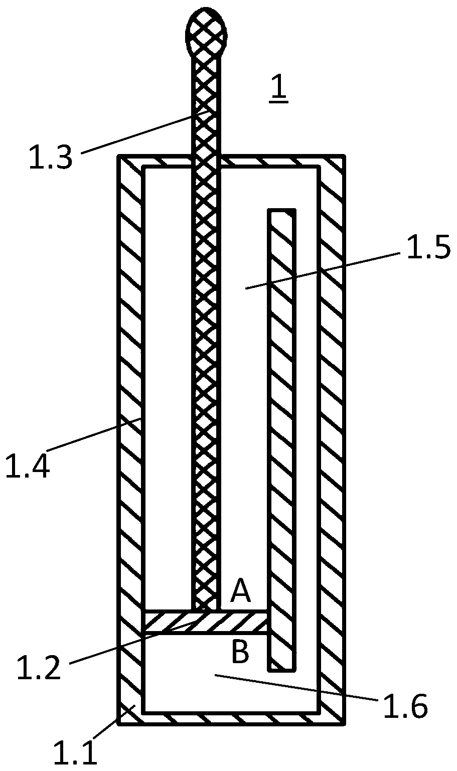
[0077] In this embodiment, only the above-mentioned improved pressure cylinder is used to provide output force for the lifting platform, and the pressure cylinder is arranged under the table. According to the stress on the table, only a single pressure cylinder can be provided to support the table, or multiple pressure cylinders can be arranged to distribute under the table to provide output force and support.
Embodiment 2
[0079] In this embodiment, the above-mentioned improved pressure cylinder constitutes the lifting support device, and the lifting support device is used in pairs; in order to enable a pair of lifting support devices to rise and fall synchronously, each pair of lifting support devices is connected with a pair of synchronous lifting devices. A synchronous lifting device includes a pair of synchronous drives and a synchronous controller.
[0080] Synchronous lifting device
[0081] Figure 4 It is a structural schematic diagram of a single synchronous drive 2.1. A synchronous drive 2.1 includes a strip-shaped support frame 2.11, and the two ends of the support frame 2.11 are provided with phase connectors 2.14 with transmission wheels, and the transmission wheels of the phase connectors 2.14 at both ends are provided with The transmission chain 2.12 is provided with a synchronous connector 2.13 on the transmission chain 2.12. The synchronous connector 2.13 performs reciprocat...
Embodiment 3
[0093] In this embodiment, an energy conversion device is added on the basis of the second embodiment, and the energy conversion device provides auxiliary power for the lifting platform to rise.
[0094] energy conversion device
[0095] refer to Figure 9-Figure 10 , The energy conversion device 4 includes a torsion spring 4.1, a worm gear assembly 4.2 and a bushing 4.3. The shaft sleeve 4.3 of the energy conversion device 4 is sleeved on the central shaft 2.21 of the synchronous controller 2.2, the torsion spring 4.1 is sleeved on the shaft sleeve 4.3, one end of the torsion spring 4.1 is connected with the worm gear of the worm gear assembly 4.2, and the other end of the torsion spring 4.1 Connected with the brake fork 2.25, when the brake fork 2.25 is locked by the brake clutch 2.24, the action process of the worm gear assembly 4.2 drives the torsion spring 4.1 to rotate around the axial direction of the sleeve 4.3 to accumulate elastic potential energy. Figure 10 Amo...
PUM
 Abstract
Description
Claims
Application Information
 - R&D
- Intellectual Property
- Life Sciences
- Materials
- Tech Scout
- Unparalleled Data Quality
- Higher Quality Content
- 60% Fewer Hallucinations
Browse by: Latest US Patents, China's latest patents, Technical Efficacy Thesaurus, Application Domain, Technology Topic, Popular Technical Reports.
© 2025 PatSnap. All rights reserved.Legal|Privacy policy|Modern Slavery Act Transparency Statement|Sitemap|About US| Contact US: help@patsnap.com


