
Heightening device for crane

A crane and side plate technology, applied in the field of crane heightening devices, can solve the problems of high cost, high requirements for hydraulic equipment, and increased lifting height, etc.

Active Publication Date: 2018-06-05
徐州天骋智能科技有限公司
View PDF8 Cites 0 Cited by
  • Summary
  • Abstract
  • Description
  • Claims
  • Application Information

AI Technical Summary

Problems solved by technology

[0002] The development and use of cranes in the market are becoming more and more extensive. With the rapid development of my country's construction industry, cranes have been widely used in engineering sites. Cranes can be divided into tower type and gantry type. Among them, gantry cranes are stable and safe in structure. However, the lifting at a fixed height limits its application. The main way to increase the lifting height of the crane in the prior art is to install a hydraulic lifter at the outrigger position to lift the crane as a whole. It is easy to lose balance, causing safety accidents, and has the disadvantages of high requirements for hydraulic equipment and high cost

Method used


Image

  • Heightening device for crane
  • Heightening device for crane
  • Heightening device for crane

Examples


Embodiment Construction

[0019] The present invention will be described in further detail below by means of specific embodiments:

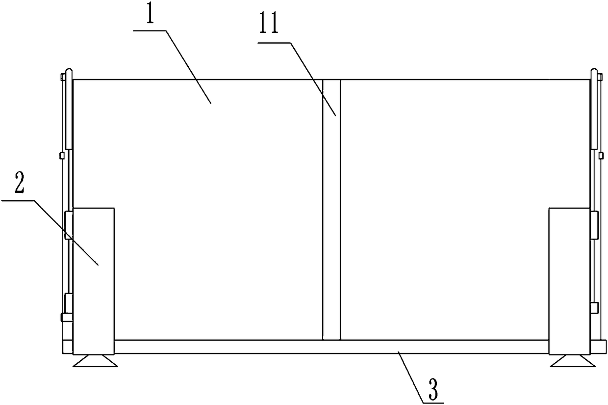
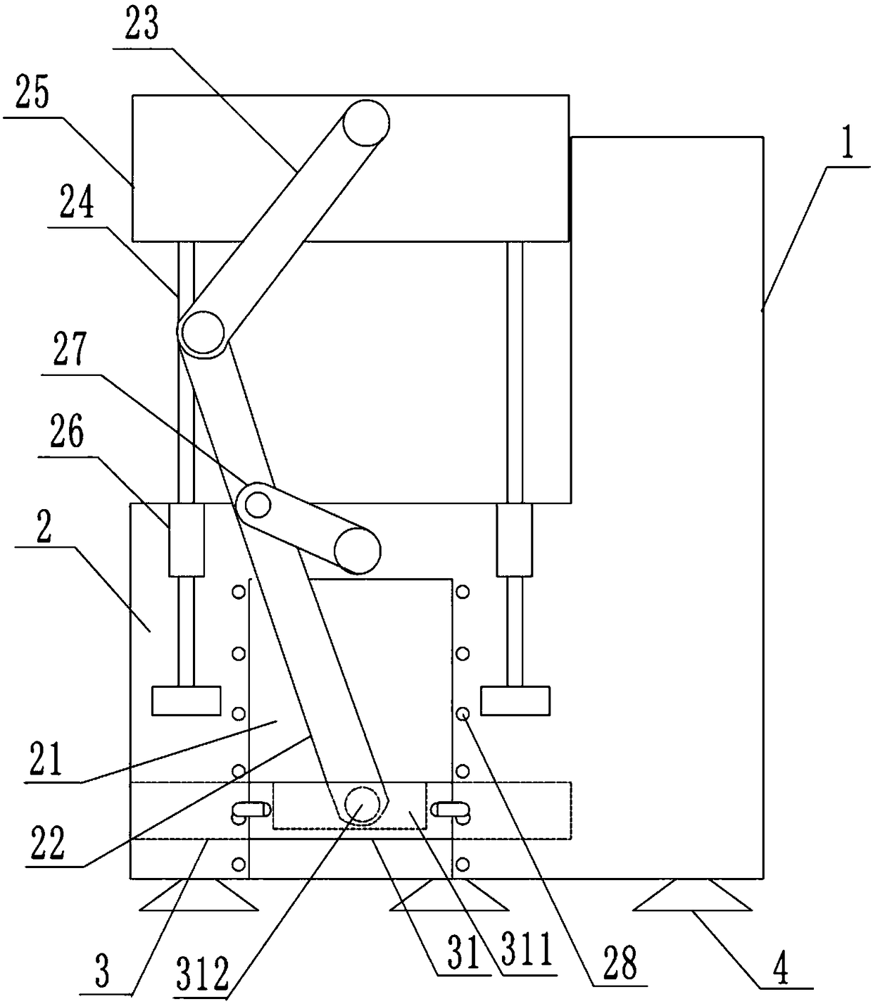
[0020] The reference signs in the accompanying drawings of the description include: back plate 1, strip groove 11, side plate 2, chute 21, swing rod 22, push rod 23, slide rod 24, baffle plate 25, limit shaft 26, rotation rod 27. Positioning hole 28, bottom plate 3, sliding block 31, swing groove 311, fixed shaft 312, suction cup 4, bar body 5, positioning column 51.

[0021] Such as figure 1 and figure 2 Shown, in order to achieve the above object, basic scheme of the present invention is as follows:

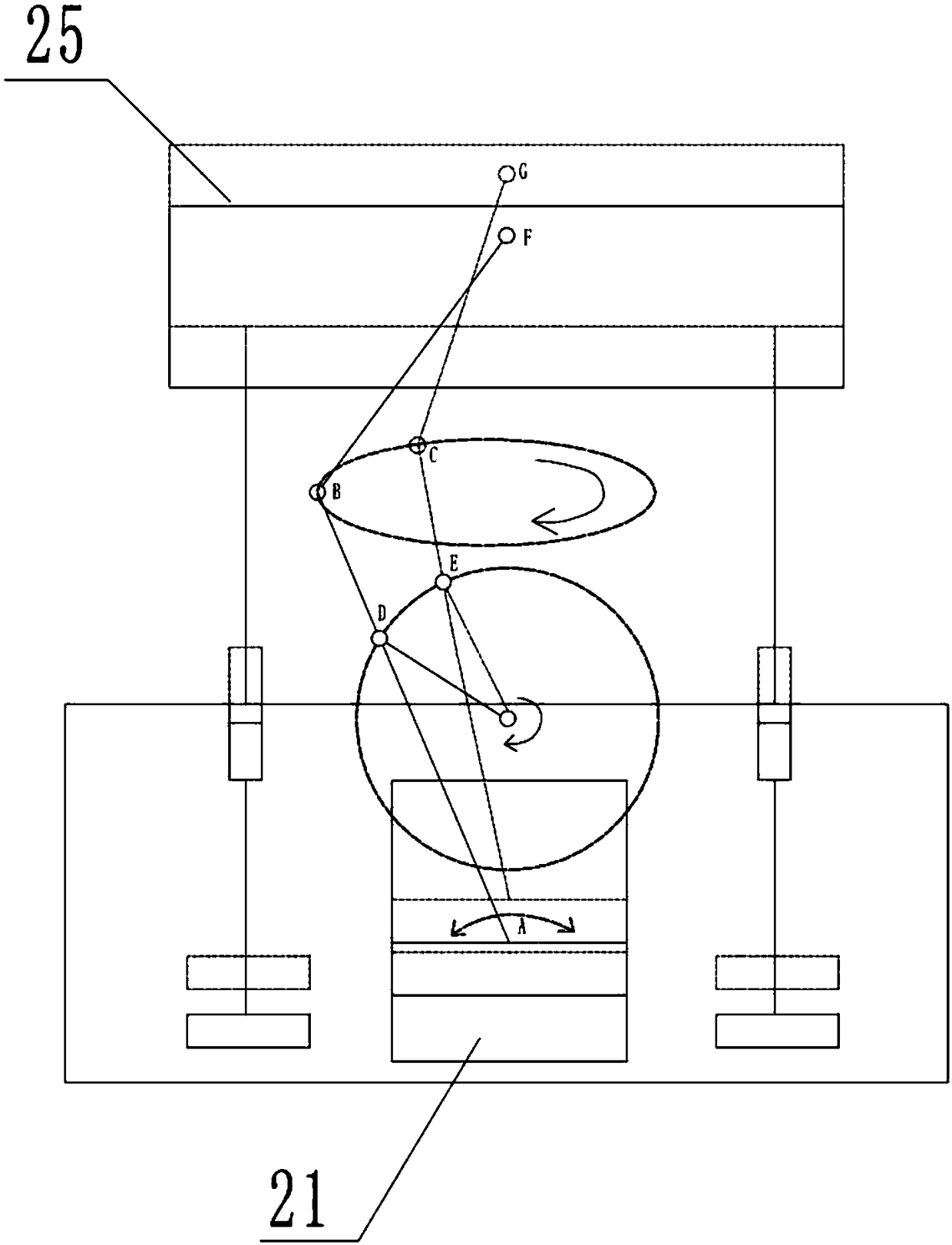
[0022] The crane heightening device comprises a backboard 1 and two sideboards 2 fixedly connected to both sides of the backboard 1, and the side view of the backboard 1 and the sideboards 2 is L-shaped. A bottom plate 3 is slidably connected between the two side plates 2; the side plates 2 are provided with chute 21, swing bar 22, push bar 23, slide bar 24, baffle pla...


PUM


Abstract

The invention relates to the technical field of a bottom supporting structure with supporting legs, and particularly relates to a heightening device for a crane. The device comprises a back plate andside plates, wherein a bottom plate is in sliding connection between the two side plates; a sliding chute, a swing rod, a push rod, slide rods, a baffle, spacing shafts, a motor and a rotating rod driven by the motor are arranged on the side plates; slide blocks are fixedly connected on two sides of the bottom plate, are used for extending into the sliding chute and are in sliding connection withthe sliding chute; a swing groove is formed in the slide block; a fixed shaft is fixedly connected to the wall of the sliding chute; one end of the swing rod is in rotating connection with the fixed shaft, and the other end of the swing rod is hinged with one end of the push rod; the swing rod is hinged with the baffle; slide rods are arranged on two sides of the bottom of the baffle; the motor isarranged above the sliding chute; the rotating rod is fixedly connected with the motor; the other end of the rotating rod is hinged with the swing rod; spacing shafts are arranged on two sides of theside plates, and the slide rods pass through the spacing shafts and are in sliding connection with the spacing shafts. According to the scheme, the balance of a crane can be kept in the process of heightening the crane.

Description

technical field [0001] The invention relates to the technical field of bottom support structures with outriggers, in particular to a crane heightening device. Background technique [0002] The development and use of cranes in the market are becoming more and more extensive. With the rapid development of my country's construction industry, cranes have been widely used in engineering sites. Cranes can be divided into tower type and gantry type. Among them, gantry cranes are stable and safe in structure. However, the lifting at a fixed height limits its application. The main way to increase the lifting height of the crane in the prior art is to install a hydraulic lifter at the outrigger position to lift the crane as a whole. It is easy to lose balance, causing safety accidents, and has the disadvantages of high requirements for hydraulic equipment and high cost. Contents of the invention [0003] The object of the present invention is to provide a crane heightening device, wh...

Claims


Application Information

Patent Timeline
IPC IPC(8): B66C13/00
CPCB66C13/00
Inventor 寇瑞东
Owner 徐州天骋智能科技有限公司
Learn More