
Cloth rolling machine

A cloth rolling machine and material rolling technology, which is applied in the direction of winding strips, thin material processing, transportation and packaging, etc., can solve the problems of excessive cloth rolling speed, uneven fabric, fabric wrinkles, etc., and achieve a simple overall structure, Ensure smooth and uniform rolling effect

Active Publication Date: 2018-06-05
ANHUI HUAYE ADVANCED MATERIALS CO LTD
View PDF21 Cites 10 Cited by
  • Summary
  • Abstract
  • Description
  • Claims
  • Application Information

AI Technical Summary

Problems solved by technology

[0002] After the industrial cloth is produced, it usually needs to be packed into rolls by a cloth rolling machine for transportation and handling. However, the structure and function of the existing cloth rolling machines are relatively simple, and the edges of the rolled industrial cloth are not neat enough, and the rolling process There are often wrinkles on the surface of the fabric with individual turns. Once there is a layer of fabric that is wrinkled, it will cause the fabric to be stacked up and rolled to be uneven; It is transported to the cloth roll frame without buffering during the period, and the speed of the cloth roll is too fast, which may easily lead to uneven rolls, which will affect the overall roll efficiency and roll quality

Method used

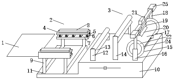

Image

  • Cloth rolling machine
  • Cloth rolling machine
  • Cloth rolling machine

Examples


Embodiment Construction

[0018] Attached below Figure 1-4 The structure, principle and working process of the present invention will be further described with specific embodiments, but the protection scope of the present invention is not limited thereto.

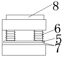
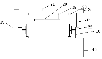
[0019] A cloth rolling machine, including a conveyor belt 1, a front positioning device 2 and a rear coiling device 3 arranged in sequence from left to right, the front positioning device 2 includes two positioning splints 4 with the same structure opposite to each other , the positioning splint 4 is "⊏" shape, the positioning splint 4 includes an upper end splint, a lower end splint and a connecting plate connecting the upper end splint and the left side of the lower end splint, and the bottom of the upper end splint is parallel to the The upper end splint is connected with several pressing plates 5, and the pressing plate 5 is a cuboid sheet structure, and the two ends of the pressing plate 5 are respectively connected to the bottom surface of th...


PUM


Abstract

The invention provides a cloth rolling machine which sequentially comprises a conveying belt, a front locating device and a rear rolling device sequentially from left to right. The front locating device comprises two locating clamping plates which are arranged oppositely front and back and are the same in structure. The locating clamping plates are shaped like a question mark. Each locating clamping plate comprises an upper end clamping plate, a lower end clamping plate and a connecting plate for connecting the left side of the upper end clamping plate and the left side of the lower end clamping plate. Multiple pressing plates are connected to the portion, parallel to the corresponding upper end clamping plate, of the bottom of each upper end clamping plate. The two ends of each pressing plate are connected to the bottom surface of each upper end clamping plate through an adjusting rod. The tops of the locating clamping plates are provided with air cylinders for controlling the adjusting rods to telescope. The rear rolling device comprises a first guide frame, a second guide frame and a cloth rolling frame. The cloth rolling machine has the beneficial effects that the overall structure is simple, the industry cloth rolling efficiency is extremely high, the edges of rolled cloth are uniform, and wrinkling of a cloth body is avoided.

Description

technical field [0001] The invention relates to the field of industrial cloth production, in particular to a cloth rolling machine. Background technique [0002] After the industrial cloth is produced, it usually needs to be packed into rolls by a cloth rolling machine for transportation and handling. However, the structure and function of the existing cloth rolling machines are relatively simple, and the edges of the rolled industrial cloth are not neat enough, and the rolling process There are often wrinkles on the surface of the fabric with individual turns. Once there is a layer of fabric that is wrinkled, it will cause the fabric to be stacked up and rolled to be uneven; It is transported to the cloth roll frame without buffering during the process, and the speed of the cloth roll is too fast, which will easily lead to uneven roll, which will affect the overall roll efficiency and roll quality. Contents of the invention [0003] The object of the present invention is...

Claims


Application Information

Patent Timeline
Patent Type & Authority Applications(China)
IPC IPC(8): B65H20/06B65H23/26B65H20/16
CPCB65H20/06B65H20/16B65H23/26
Inventor 姜辉
Owner ANHUI HUAYE ADVANCED MATERIALS CO LTD
Learn More