Novel automatic water body detection device

A detection device and water body technology, applied in transportation and packaging, underwater operation equipment, ships, etc., can solve the problems of poor flexibility and reliability of water body detection operations, continuous operation of water body detection equipment, and impact on resource utilization, and achieve the goal of using The effect of flexibility and convenience, high degree of modularization, and simple equipment structure

Active Publication Date: 2018-06-05
JIAOZUO UNIV
View PDF6 Cites 3 Cited by
  • Summary
  • Abstract
  • Description
  • Claims
  • Application Information

AI Technical Summary

Problems solved by technology

[0002] At present, in the water body detection operation, the water quality detection equipment used is often installed on the embankment, the bottom of the water body and the carrying equipment floating on the surface of the water body through the positioning mechanism. Although it can meet the needs of use, but As a result, the flexibility and reliability of water body detection operations are relatively poor, and it is impossible to flexibly adjust the detection equipment to the needs of water body detection operations in different locations according to the needs of use. At the same time, the current water body detection equipment needs to pass the External equipment provides the power required for its operation, which also leads to the continuous operation of the current water body detection equipment and the great impact on resource utilization. To solve this problem, it is urgent to develop a new water body detection equipment to meet practical needs

Method used


Image

  • Novel automatic water body detection device
  • Novel automatic water body detection device
  • Novel automatic water body detection device

Examples


Embodiment Construction

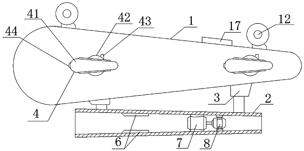
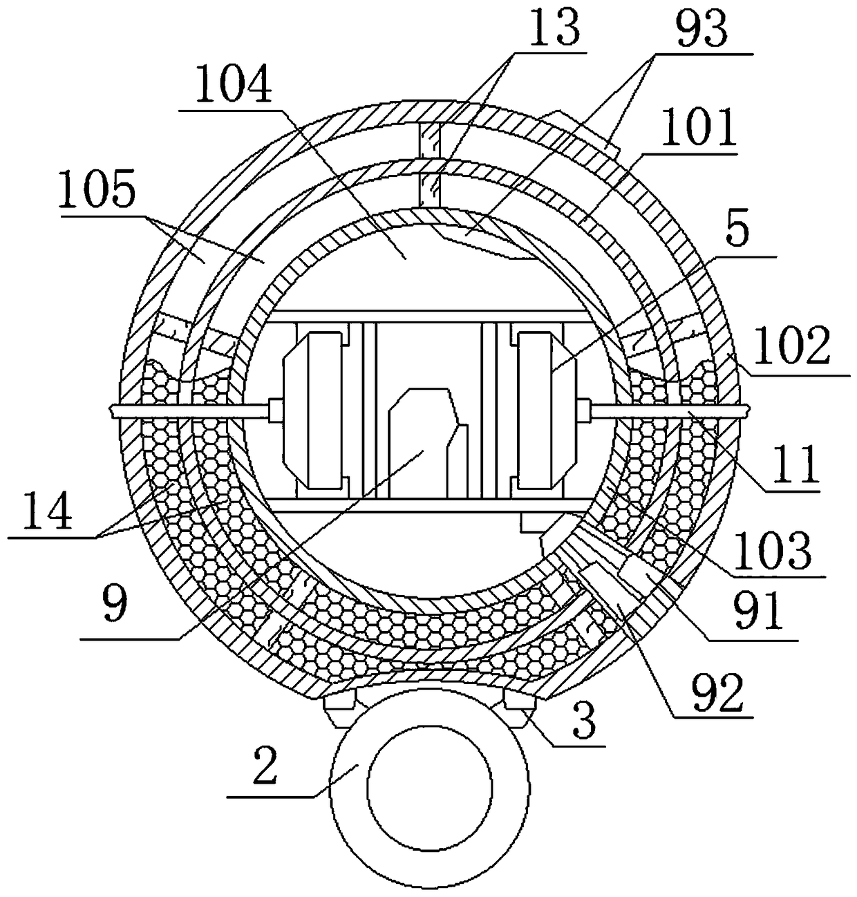
[0017] Such as figure 1 , 2 As shown in and 3, a new type of automatic water body detection device includes a bearing base 1, a diversion tube 2, a lifting drive mechanism 3, an adjustment plate 4, an adjustment motor 5, a detection sensor 6, a driving impeller 7, a driving motor 8 and a control circuit 9. The load-bearing base 1 includes a load-bearing keel 101, a sealing protection layer 102, and a load-bearing liner 103. The seal protection layer 102 is coated on the outer surface of the load-bearing keel 101, and the load-bearing liner 103 is embedded in the load-bearing keel 101. The sealing protection layer 102, load-bearing The inner tanks 103 are all of closed cavity structure and coaxial with each other. The bearing inner tank 103 constitutes the bearing chamber 104, and the sealing protection layer 102 and the bearing inner tank 103 form a buffer chamber 105. The control circuit 9 and the adjusting motor 5 are embedded in the load bearing chamber. cavity 104, and th...


PUM


Abstract

The invention relates to a novel automatic water body detection device. The novel automatic water body detection device comprises a bearing base body, a flow guide pipe, a hoisting driving mechanism,an adjusting plate, an adjusting motor, a detection sensor, a driving impeller, a driving motor and a control circuit, wherein the bearing base body comprises a bearing keel, a sealing protection layer and a bearing liner; the control circuit and the adjusting motor are embedded into a bearing cavity; the control circuit is electrically connected with the hoisting driving mechanism, the adjustingplate, the adjusting motor, the detection sensor and the driving motor respectively; the adjusting plate comprises a flow guide plate, a rotary platform mechanism, an angle sensor and a pressure sensor; the flow guide pipe is mounted on the outer surface of the bearing base body through the hoisting driving mechanism; the detection sensor, the driving impeller and the driving motor are embedded into the flow guide pipe. According to the novel automatic water body detection device provided by the invention, on one hand, the requirements of automatically carrying out water body detection work under water for a long time can be effectively met, the operation energy consumption is low and the comprehensive utilization rate of resources can be effectively improved; on the other hand, an operation state and a position in a water body can be flexibly and automatically adjusted.

Description

technical field [0001] The invention relates to a novel automatic water body detection device, which belongs to the technical field of water quality monitoring. Background technique [0002] At present, in the water body detection operation, the water quality detection equipment used is often installed on the embankment, the bottom of the water body and the carrying equipment floating on the surface of the water body through the positioning mechanism. Although it can meet the needs of use, but As a result, the flexibility and reliability of water body detection operations are relatively poor, and it is impossible to flexibly adjust the detection equipment to the needs of water body detection operations in different locations according to the needs of use. At the same time, the current water body detection equipment needs to pass the External equipment provides the power required for its operation, which also leads to the continuous operation of the current water body detecti...

Claims


Application Information

Patent Timeline
Patent Type & Authority Applications(China)
IPC IPC(8): B63C11/52
CPCB63C11/52
Inventor 刘云朋赵锋拜亚萌靳孝峰司国斌
Owner JIAOZUO UNIV
Why Eureka
Try Eureka