Fixing device used for construction carpenter and facilitating adjusting angular position of wood

A technology of angle position and fixing device, which is applied in the direction of workpiece clamping device, wood processing equipment, manufacturing tools, etc., can solve problems such as troublesome, not stable enough, inconvenient to handle, etc.

Inactive Publication Date: 2018-06-05
ZHENGZHOU MOORE ELECTRONICS INFORMATION TECH CO LTD
View PDF11 Cites 4 Cited by
  • Summary
  • Abstract
  • Description
  • Claims
  • Application Information

AI Technical Summary

Problems solved by technology

[0002] During the construction process on the construction site, many things need to be done, such as building walls, painting, tying steel bars, wood processing, etc. Each kind of operation requires special workers to carry out the work, and the tools they use are also It is not the same, but woodworkers mainly use pin knives to exploit the end face of wood when processing wood. When exploiting, first of all, it is necessary to hold down the wood with hands to prevent the position of the wood from shifting and sliding during the exploitation process, which will affect the size after exploitation. It is laborious to hold down by hand like this, it is not stable enough, and sometimes due to the problem of the position of the board being processed, the board cannot be placed stably, resulting in inconvenient handling, and a lot of wood chips will be generated during the exploitation process, generally these wood chips are It is randomly scattered on the job site, and the fine wood chips will be scattered in the air, which will affect the health of workers after inhalation, and the large wood chips randomly scattered on the job site need to be cleaned and disposed of by workers, which is troublesome

Method used

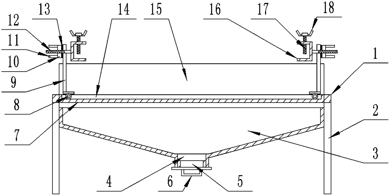
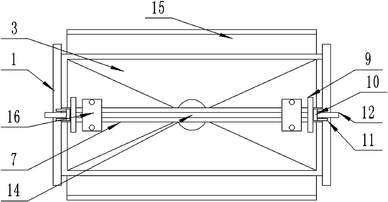
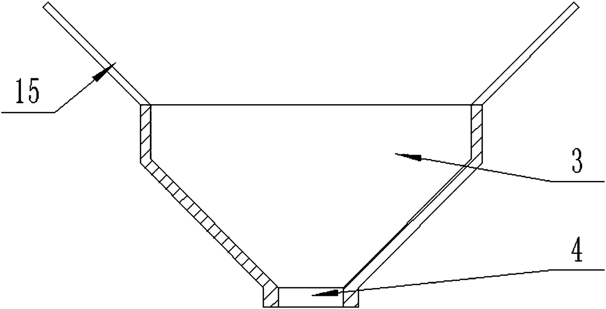

Image

  • Fixing device used for construction carpenter and facilitating adjusting angular position of wood
  • Fixing device used for construction carpenter and facilitating adjusting angular position of wood
  • Fixing device used for construction carpenter and facilitating adjusting angular position of wood

Examples


Embodiment Construction

[0016] The technical solution of this patent will be further described in detail below in conjunction with specific embodiments.

[0017] Embodiments of the present patent are described in detail below, examples of which are shown in the drawings, wherein the same or similar reference numerals designate the same or similar elements or elements having the same or similar functions throughout. The embodiments described below by referring to the figures are exemplary and are only used for explaining the patent, and should not be construed as limiting the patent.

[0018] In the description of this patent, it is to be understood that the terms "center", "upper", "lower", "front", "rear", "left", "right", "vertical", "horizontal", The orientation or positional relationship indicated by "top", "bottom", "inner", "outer", etc. is based on the orientation or positional relationship shown in the drawings, and is only for the convenience of describing this patent and simplifying the des...


PUM


Abstract

The invention provides a fixing device used for a construction carpenter and facilitating adjusting an angular position of wood, and belongs to the field of construction carpentry. The fixing device comprises two connecting bars that are horizontally distributed on the left side and the right side and parallel to each other; and support legs are vertically and fixedly connected with the lower sides of the ends of the two connecting bars. According to the device, the support legs support the connecting bars; pulleys drive two slide plates to slide to left and right along a strip-shaped slide groove to adjust a distance between the slide plates; when a wood plate is treated, the distance between the two slide plates is adjusted in a sliding manner according to the length of the wood plate; the two ends of the wood plate are clamped in U-shaped clamp frames respectively; first threaded rods rotationally moves downwards and push against the ends, clamped in the U-shaped clamp frames, of the plate; the plate is fixed between the U-shaped clamp frame; then, a tool is used for plate treatment; the U-shaped clamp frames of the plate are fixed by rotating rotating shafts between the U-shaped clamp frames and the slide plates; the angular position of the plate is adjusted; and the treatment is facilitated.

Description

technical field [0001] The invention relates to a building woodworking tool, in particular to a fixing device for building woodworking which is convenient for adjusting the angular position of wood. Background technique [0002] During the construction process on the construction site, many things need to be done, such as building walls, painting, tying steel bars, wood processing, etc. Each kind of operation requires special workers to carry out the work, and the tools they use are also It is not the same, but woodworkers mainly use pin knives to exploit the end face of wood when processing wood. When exploiting, first of all, it is necessary to hold down the wood with hands to prevent the position of the wood from shifting and sliding during the exploitation process, which will affect the size after exploitation. It is laborious to hold down by hand like this, it is not stable enough, and sometimes due to the problem of the position of the board being processed, the board ...

Claims


Application Information

Patent Timeline
Patent Type & Authority Applications(China)
IPC IPC(8): B27C9/00B25B11/00B27G3/00
CPCB25B11/00B27C9/00B27G3/00
Inventor 邢济祥
Owner ZHENGZHOU MOORE ELECTRONICS INFORMATION TECH CO LTD
Why Eureka
Try Eureka