Abrasive flow machining die for uniform polishing of inner wall of cross-hole workpiece and calculating method of cores of abrasive flow machining die

A cross-hole and abrasive flow technology, which is applied in the direction of grinding/polishing equipment, surface polishing machine tools, machine tools suitable for grinding workpiece edges, etc. Problems such as equal margin and uniform polishing have not been realized, so as to ensure the polishing quality and improve the polishing efficiency

Active Publication Date: 2018-06-05
DALIAN UNIV OF TECH
View PDF7 Cites 4 Cited by
  • Summary
  • Abstract
  • Description
  • Claims
  • Application Information

AI Technical Summary

Problems solved by technology

The disadvantage of this method is that the vicinity of the part burr is also subjected to electrolysis, and the polished surface will lose the original luster of the material, and even affect the dimensional accuracy of the part
[0005] "Research on Abrasive Flow Uniform Machining Method for Special-shaped Inner Hole Surface" published by Zhang Kehua et al. proposed a method to uniformly process special-shaped surfaces by setting similar core structures to improve the distribution of shear stress. The mold core structure only makes the material removal of the same cross-section of the part almost uniform, but there is an "over-throwing" problem at the entrance and exit of the part. From the perspective of the part as a whole, equal margin and uniform polishing have not been achieved, which is harmful to some surfaces. Parts with high quality consistency requirements do not meet their use requirements

Method used


Image

  • Abrasive flow machining die for uniform polishing of inner wall of cross-hole workpiece and calculating method of cores of abrasive flow machining die
  • Abrasive flow machining die for uniform polishing of inner wall of cross-hole workpiece and calculating method of cores of abrasive flow machining die
  • Abrasive flow machining die for uniform polishing of inner wall of cross-hole workpiece and calculating method of cores of abrasive flow machining die

Examples


Embodiment Construction

[0066] The specific implementation manners of the present invention will be further described below in conjunction with technical solutions, specific embodiments and accompanying drawings.

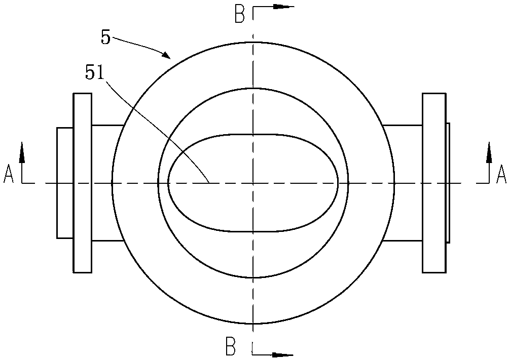
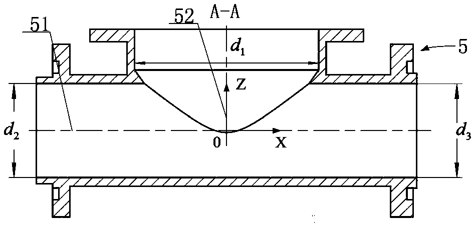
[0067] like figure 1 Shown is the structure of the uniform polishing mold with a cross-shaped cross-hole workpiece abrasive grain flow and the flow of the abrasive medium. In this embodiment, a "T"-shaped cross-hole part is used as the cross-hole workpiece 5. Its structure is as follows Figure 2-4 shown. designed as Figure 5-13 A "T" shaped cross-hole workpiece inner wall abrasive flow uniform polishing mold is shown, including the flow channel control unit A2, the flow channel control unit B3, the flow channel control unit C4 and the sealing device;

[0068] The number of the flow channel control unit is the same as the number of orifices of the cross hole workpiece 5, i.e. three; each flow channel control unit corresponds to the orifice of a cross hole workpiece 5; the flow channel c...


PUM


Abstract

The invention discloses an abrasive flow machining die for uniform polishing of the inner wall of a cross-hole workpiece and a calculating method of cores of the abrasive flow machining die. The abrasive flow machining die comprises a plurality of passage control units and sealing devices; each passage control unit comprises a transition segment, a guide segment and a core; the passage control units are as many as orifices of a cross-hole workpiece; each passage control unit corresponds to one orifice of the cross-hole workpiece; the passage control units are divided into two groups connectedrespectively with cylinder A and cylinder B in an abrasive flow machining apparatus. The transition segment is arranged at each orifice of a cross-hole workpiece, so that the influence of 'entry effect' upon the cross-hole workpiece is effectively avoided, and the problem that the orifices of the cross-hole workpiece experiences 'over-polishing' is solved. For a cross-hole workpiece, die cores capable of providing equal-allowance uniform polishing for the inner wall of the cross-hole workpiece is are designed; the problem that the cross-hole workpiece experiences non-uniform polishing is solved; polishing quality can be effectively guaranteed, and polishing efficiency can be effectively improved.

Description

technical field [0001] The invention belongs to the field of mechanical manufacturing, and relates to a calculation method for uniformly polishing a mold and a mold core thereof by abrasive flow applied to the inner wall of a cross-hole workpiece. Background technique [0002] Cross-hole workpieces are more and more widely used in aviation, aerospace and other fields. Such parts are usually formed by intersecting variable-diameter or equal-diameter pipes with circular cross-sections. The overall structure is "X", "Y", "T ", "ten" and other structures ( Figure 2-4 Shown is a schematic diagram of a "T" shaped cross-hole workpiece). In order to meet the requirement that the inner wall of such parts is not allowed to have burrs and other easy-to-fall particles during use, the inner wall of such parts is usually polished in the last process. Due to the geometric interference between the polishing abrasive and the cross-hole workpiece and the complicated trajectory of the polish...

Claims


Application Information

Patent Timeline
IPC IPC(8): B24B31/116G06F17/50
CPCB24B31/116G06F30/17G06F30/20G06F2111/10
Inventor 高航彭灿王宣平魏海波王海全
Owner DALIAN UNIV OF TECH
Why Eureka
Try Eureka