
Switch control method and system, switch control device and test device

A technology of switch control and equipment, applied in the direction of measuring devices, electric switches, power supply testing, etc., can solve problems such as low efficiency

Active Publication Date: 2021-05-28
GUANGZHOU GRG METROLOGY & TEST CO LTD +1
View PDF11 Cites 0 Cited by
  • Summary
  • Abstract
  • Description
  • Claims
  • Application Information

AI Technical Summary

Problems solved by technology

[0005] Based on this, it is necessary to provide a switch control method for the problem of low efficiency of switch control in traditional technology

Method used


Image

  • Switch control method and system, switch control device and test device
  • Switch control method and system, switch control device and test device
  • Switch control method and system, switch control device and test device

Examples


Embodiment Construction

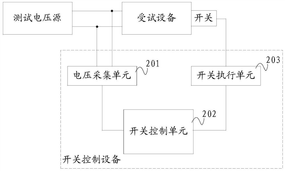
[0053] The specific implementation of the switch control method of the present invention will be described in detail below in conjunction with the accompanying drawings.

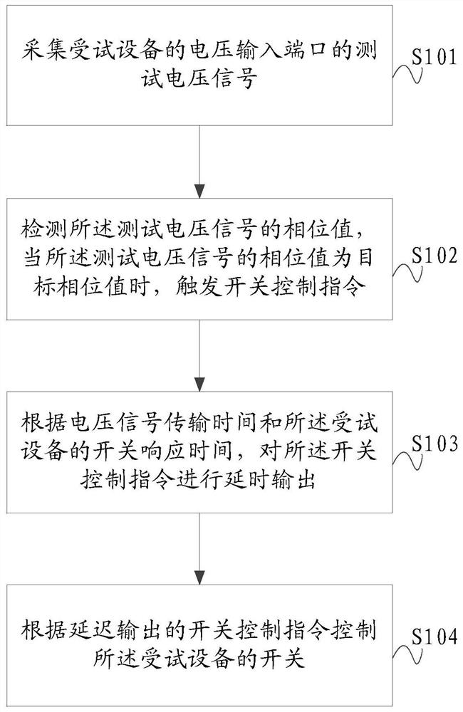
[0054] In one embodiment, a switch control method is provided, referring to figure 1 said, figure 1 It is a flow chart of the switch control method in one embodiment, including the following steps:

[0055] Step S101, collecting the test voltage signal of the voltage input port of the device under test;

[0056] Wherein, the test voltage signal refers to the test voltage signal input by the test voltage source to the voltage input port of the device under test when the device under test is tested, and the test voltage signal may include voltage signals of sine wave, square wave or triangular wave.

[0057]This step is mainly to collect the test voltage signal at the voltage input port of the device under test, and then obtain information such as voltage amplitude, phase value, frequency or period of the te...


PUM


Abstract

The invention relates to a switch control method, comprising the steps of: collecting a test voltage signal of a voltage input port of a device under test; detecting a phase value of the test voltage signal, and when the phase value of the test voltage signal is a target phase value, Triggering the switch control instruction; according to the voltage signal transmission time and the switch response time of the device under test, delaying the output of the switch control instruction; wherein, the voltage signal transmission time is the test voltage signal from the voltage input port The time of transmission to the device under test; the switch of the device under test is controlled according to the delayed output switch control instruction. This scheme makes the switch of the device under test be accurately controlled by the switch control command, overcomes the problem of low efficiency of switch control in the traditional technology, improves the switch control efficiency of the device under test, and then provides a guarantee for improving the test efficiency of the device under test. Also provided are a switch control system, a switch control device and a test device.

Description

technical field [0001] The invention relates to the technical field of electronic equipment, in particular to a switch control method and system, a switch control device and a testing device. Background technique [0002] With the rapid development of electronic technology, the requirements for the quality of electronic equipment are getting higher and higher. Comprehensive testing of the performance of electronic equipment is an important way to ensure the quality of electronic equipment. [0003] Taking the electromagnetic compatibility and power supply characteristic test of electronic equipment as an example, when performing power line transient interference test on the equipment under test, the test standard requires that the switch of the equipment under test can be turned on and off accurately under various typical working conditions, and It can accurately read parameters such as the maximum value of the peak signal amplitude generated by the device under test at the ...

Claims


Application Information

Patent Timeline
Patent Type & Authority Patents(China)
IPC IPC(8): H03K17/28H01H9/54G01R29/08G01R31/40
CPCG01R29/0892G01R31/40H01H9/54H03K17/28
Inventor 代勇
Owner GUANGZHOU GRG METROLOGY & TEST CO LTD
Learn More