Current-to-voltage conversion circuit applied to commercial concrete production management system
A production management system and conversion circuit technology, applied in commercial concrete technology and electronic fields, can solve the problems of backward teaching technology, many strokes, laborious and other problems, achieve scientific design, avoid environmental pollution, and use reasonable effects
- Summary
- Abstract
- Description
- Claims
- Application Information
AI Technical Summary
Problems solved by technology
Method used
Image
Examples
Embodiment 1
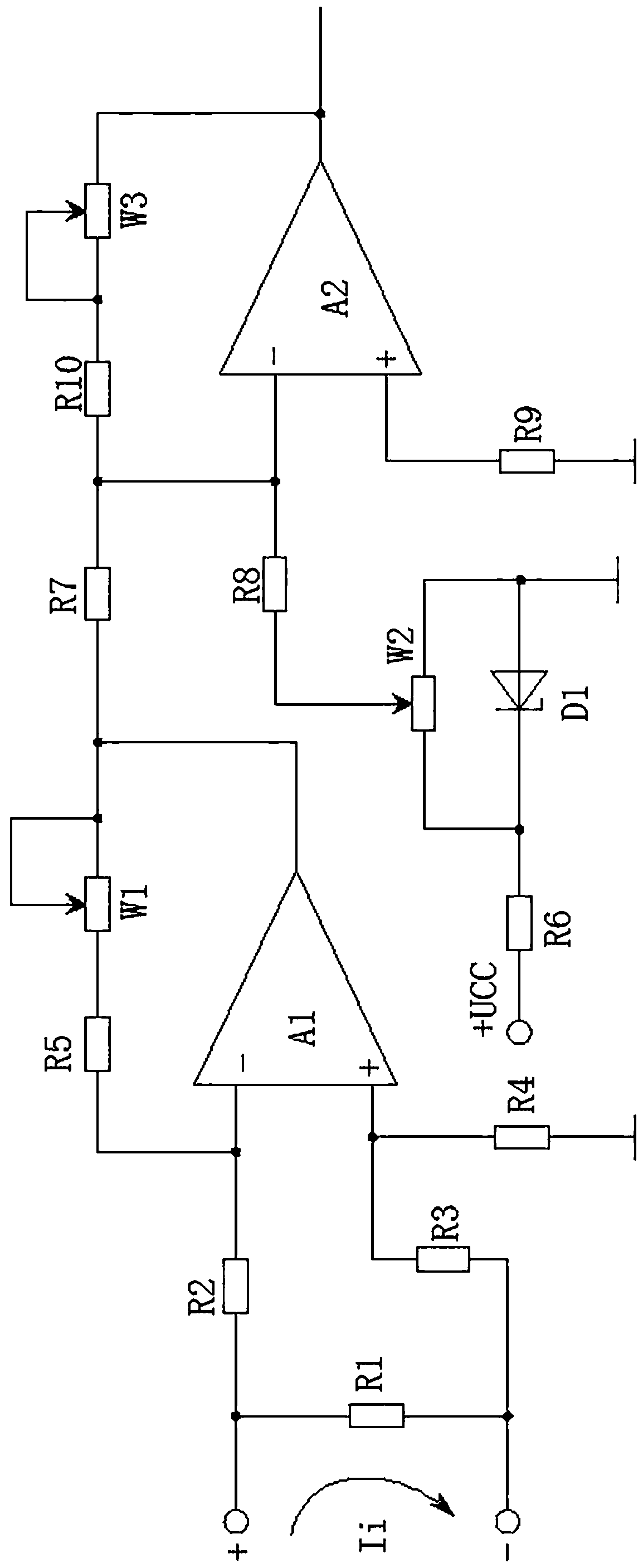
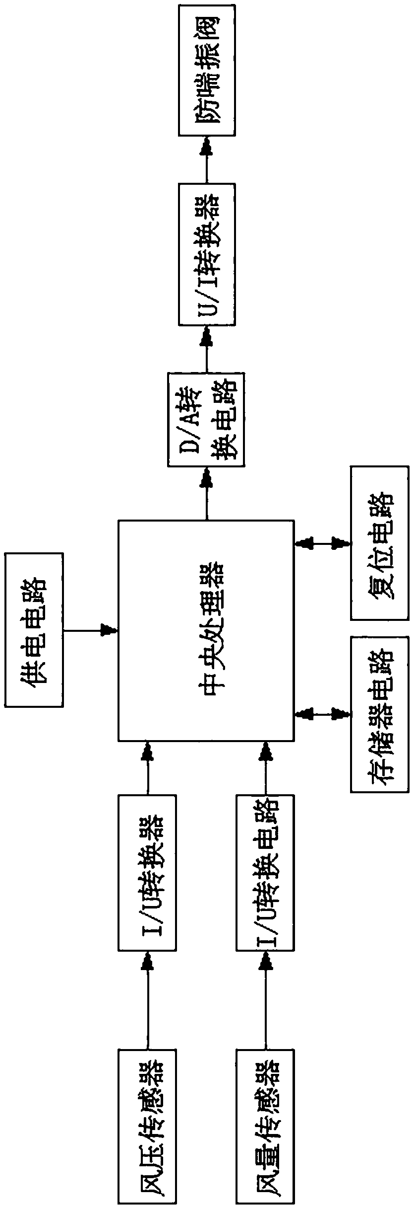
[0036] The current-voltage conversion circuit applied to the commercial concrete production management system, when producing commercial concrete, uses the I / U converter composed of two-stage current-voltage conversion circuits to convert current to voltage, and is set based on the integrated operation The design is designed to make the circuit more efficient and stable when performing current-voltage conversion, avoiding systemic failures that affect the normal operation of the entire circuit, such as figure 1 , figure 2 As shown, the following arrangement structure is adopted in particular: a central processing unit, a wind pressure circuit, an air volume circuit and an anti-surge circuit are provided, the wind pressure circuit and the air volume circuit are both connected to the central processing unit, and the central processing unit is connected to the anti-surge Breathing circuit; a wind pressure sensor and an I / U converter are arranged in the wind pressure circuit, the...
Embodiment 2
[0040] This embodiment is further optimized on the basis of the above-mentioned embodiments, further to better realize the present invention, such as figure 1 , figure 2 As shown, the following setting method is adopted in particular: a resistor R7, a resistor R8, a resistor R6, a potentiometer W2, a diode D1, a resistor R9, a resistor R10, a potentiometer W2 and an integrated operation Put A2, the output end of the integrated op amp A1 is connected to the first input end of the integrated op amp A2 through the resistor R7, the first input end of the integrated op amp A2 is connected to the integrated op amp A2 through the resistor R10 and the potentiometer W3 connected in series The output terminal of the potentiometer is connected, the diode D1 and the potentiometer W2 are connected in parallel and connected to the power supply +UCC through the resistor R6, the adjustable terminal of the potentiometer W2 is connected to the first input terminal of the integrated op amp A2 t...
Embodiment 3
[0043] This embodiment is further optimized on the basis of any of the above embodiments, further to better realize the present invention, such as figure 1 , figure 2 As shown, the following setting method is specially adopted: the resistor R2 is connected to the inverting input terminal of the integrated operational amplifier A1, the resistor R3 is connected to the non-inverting input terminal of the integrated operational amplifier A1; the cathode of the diode D1 is connected to the resistor R6, and the resistor R8 is connected to the integrated operational amplifier. Put the inverting input of A2, and the resistor R9 is connected to the non-inverting input of the integrated operational amplifier A2.
PUM
 Abstract
Description
Claims
Application Information
 - R&D Engineer
- R&D Manager
- IP Professional
- Industry Leading Data Capabilities
- Powerful AI technology
- Patent DNA Extraction
Browse by: Latest US Patents, China's latest patents, Technical Efficacy Thesaurus, Application Domain, Technology Topic, Popular Technical Reports.
© 2024 PatSnap. All rights reserved.Legal|Privacy policy|Modern Slavery Act Transparency Statement|Sitemap|About US| Contact US: help@patsnap.com


