
Electronic equipment and temperature control method thereof

A technology of electronic equipment and temperature value, applied in the direction of temperature control, branch equipment, non-electric variable control, etc., can solve problems such as affecting the utilization rate, reducing the scope of the external temperature environment, affecting the service life, etc., to enhance the user experience and increase the use of range, the effect of prolonging the service life

Inactive Publication Date: 2018-06-01
SHANGHAI YUDE TECH CO LTD
View PDF5 Cites 1 Cited by
  • Summary
  • Abstract
  • Description
  • Claims
  • Application Information

AI Technical Summary

Problems solved by technology

The camera needs to shoot and record scenes in various environments and climates. When the outside temperature is too high or too low, the battery inside the camera will be affected, causing the camera to shut down or some functions cannot be used normally, affecting users to use the camera at different extreme temperatures poor user experience, and camera battery life is also affected
Similarly, the battery and other components inside the existing electronic equipment are also affected under the extreme temperature, which reduces the external temperature environment range that the equipment can use, which affects the utilization rate, and the internal components are easily damaged by the extreme temperature, which affects the service life.

Method used


Image

  • Electronic equipment and temperature control method thereof
  • Electronic equipment and temperature control method thereof
  • Electronic equipment and temperature control method thereof

Examples


Embodiment Construction

[0029] In order to make the object, technical solution and advantages of the present invention clearer, various embodiments of the present invention will be described in detail below in conjunction with the accompanying drawings. However, those of ordinary skill in the art can understand that, in each implementation manner of the present invention, many technical details are provided for readers to better understand the present application. However, even without these technical details and various changes and modifications based on the following implementation modes, the technical solution claimed in each claim of the present application can be realized.

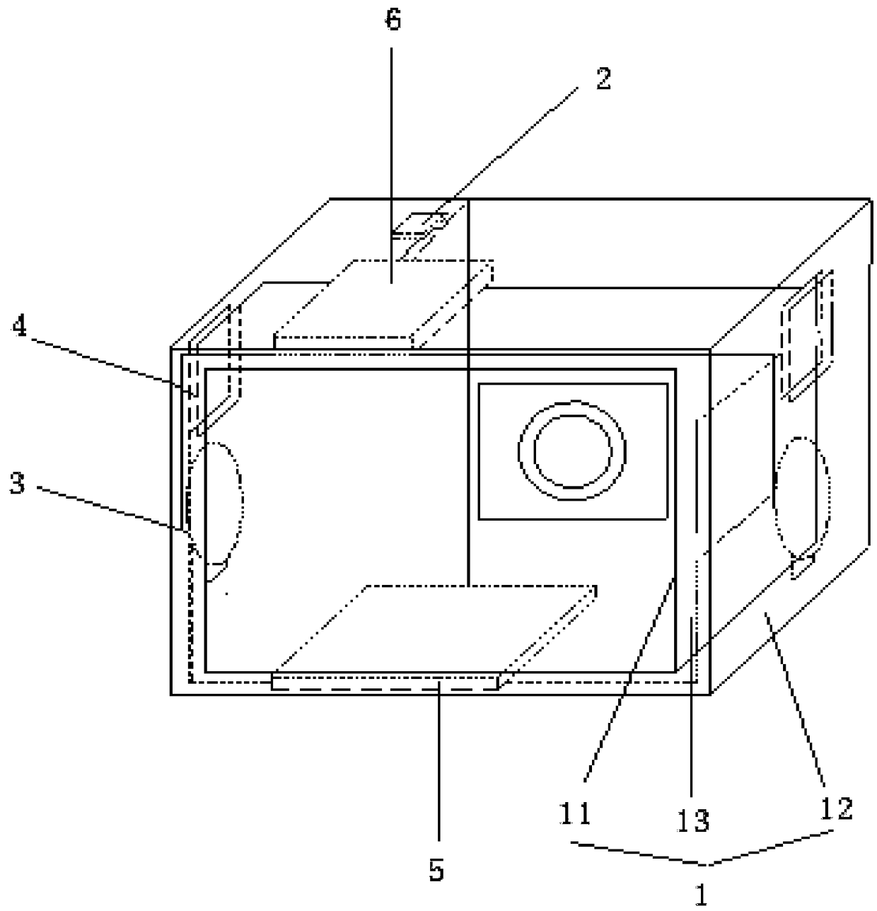
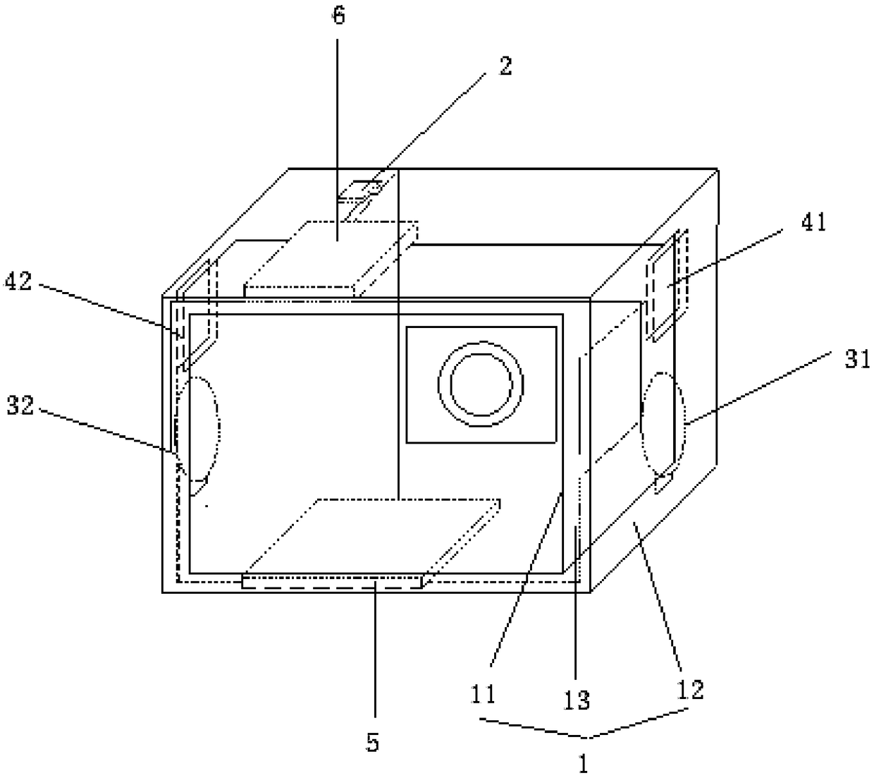
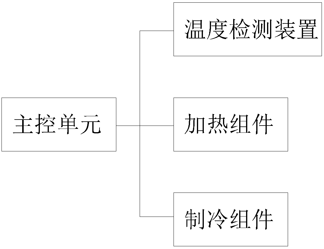
[0030] A first embodiment of the present invention relates to an electronic device. like figure 1 and image 3 As shown, the electronic device includes a casing 1 , a temperature detection device 2 , a heating component 3 , a cooling component 4 and a main control unit 6 . The casing 1 includes an inner wall 11 and an out...


PUM


Abstract

The invention relates to the field of electronic equipment, and discloses a piece of electronic equipment and a temperature control method thereof. The electronic equipment comprises a housing, a temperature detection device, a heating component, a refrigeration component, and a main control unit. The housing consists of an inner wall and an outer wall arranged opposite to the inner wall, and an interlayer area is formed between the inner wall and the outer wall. The temperature detection device is arranged in the interlayer area, and detects the temperature in the interlayer area. The heatingcomponent is arranged in the interlayer area. The refrigeration component is arranged in the interlayer area. The main control unit is electrically connected with the temperature detection device, the heating component and the refrigeration component. The main control unit opens the refrigeration component when the temperature value received is higher than an upper limit threshold, and opens theheating component when the temperature value received is lower than a lower limit threshold. Compared with the prior art, the temperature in the electronic equipment can be controlled, so that the battery and other components are protected from damage, the service life of the electronic equipment is prolonged, it is ensured that the electronic equipment can work normally at different external temperatures, the user experience is enhanced, and the use range is increased.

Description

technical field [0001] The invention relates to the field of electronic equipment, in particular to an electronic equipment and a temperature control method thereof. Background technique [0002] Electronic devices generally include mobile phones, cameras, tablet computers, etc. These devices generally need to be kept at a suitable temperature to maintain normal operation. When the extreme temperature is too high or too low, the function of some components in the device will be affected. . Taking a camera as an example, the camera uses the principle of optical imaging to form an image and uses a film to record the image. Many devices that can record images have the characteristics of photoelectric devices. Medical imaging equipment, astronomical observation equipment, etc. Photonics is an optical device used for photography. After the light reflected by the subject is focused by the camera lens and the shutter that controls the exposure, the subject forms a latent image ...

Claims


Application Information

Patent Timeline
IPC IPC(8): G05D23/20H04M1/725
CPCG05D23/20H04M1/72454
Inventor 张文馨赵普
Owner SHANGHAI YUDE TECH CO LTD
Learn More