Prefabricated fragment strip adhesive tape adhering device
A sticking device and adhesive tape technology, which is applied in the direction of weapon accessories, ammunition, offensive equipment, etc., can solve the problems of occupying human resources and slow production efficiency, and achieve the effect of improving the sticking accuracy, improving production efficiency, and reducing the shape of the tape
- Summary
- Abstract
- Description
- Claims
- Application Information
AI Technical Summary
Problems solved by technology
Method used
Image
Examples
Embodiment 1
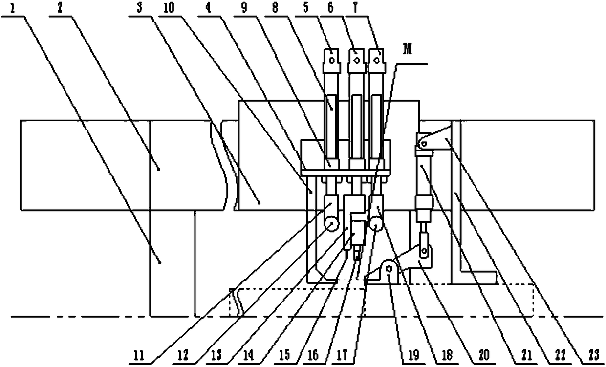
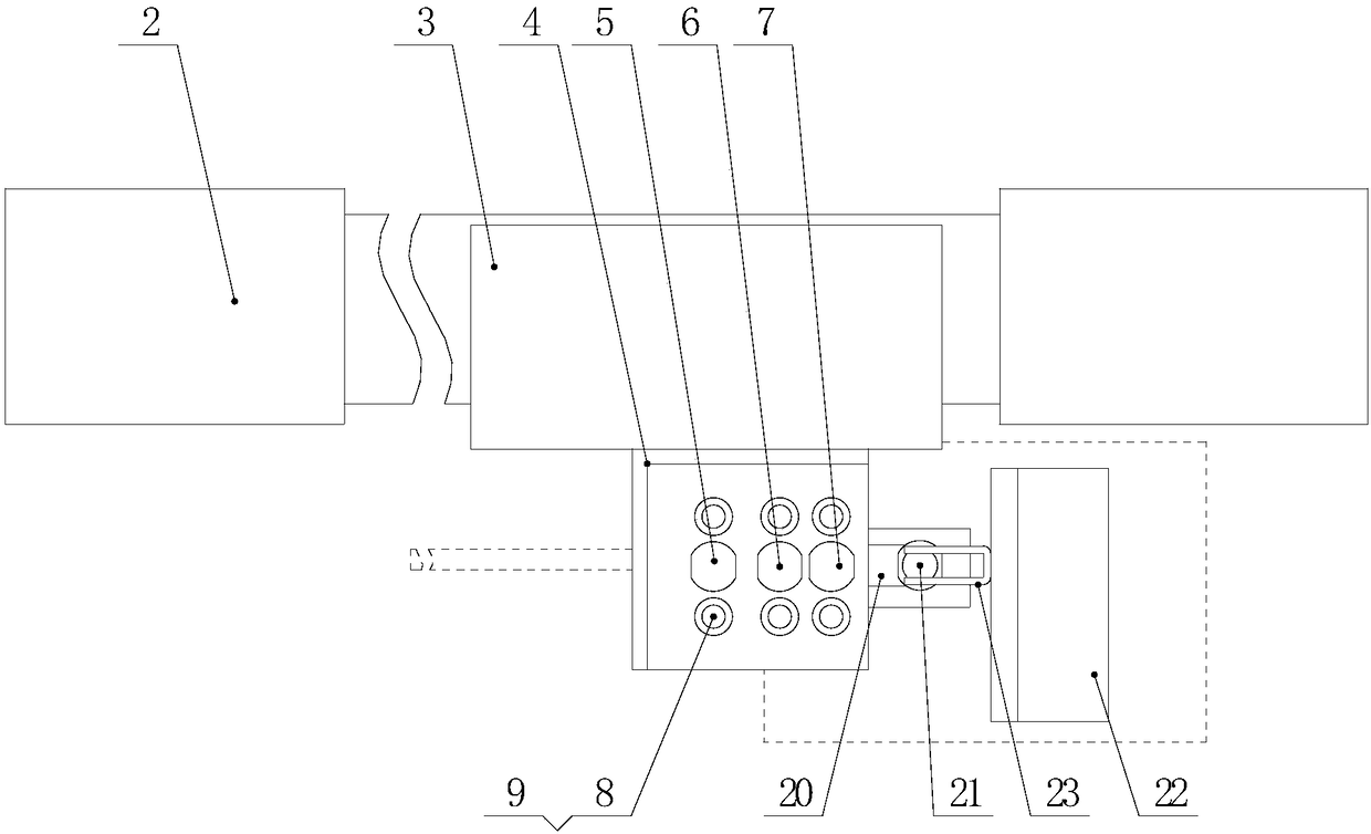
[0025] Such as figure 1 , figure 2 as shown,
[0026] A prefabricated fragment tape sticking device, comprising a frame 1, a down-pressing tape holding device, a down-pressing cutter device, a down-pressing glue device, and a tape end clip located on the A side of the frame and arranged in sequence along the advancing direction of the tape. The holding device, and the down-pressing tape holding device, the down-pressing cutter device, and the down-pressing glue device are all located directly above the advancing path of the tape, and the tape end clamping device is provided with a jaw located on the advancing path of the tape.
[0027] The design scheme of the present invention is: respectively install a pressure tape holding device, a downward pressure cutter device, and a downward pressure glue pressing device directly above the advancing path of the tape, wherein when the tape advances to the tape end clamping device, the tape end clamp The clamp of the holding device cl...
Embodiment 2
[0029] On the basis of the above-mentioned embodiment, preferably, the servo electric cylinder 2 is installed on the frame 1, and also includes a translation plate 3, the translation plate 3 is connected with the servo electric cylinder 2 and controlled by the output shaft of the servo electric cylinder 2 along the X Move in the horizontal direction, and the X horizontal direction is parallel to the advancing path of the tape. The press-down tape holding device, the press-down cutter device, and the press-down adhesive device are all installed on the translation plate 3 to link with the translation plate 3, and the press-down tape remains The device, the lower pressure cutter device, and the lower pressure glue device all contain air cylinders, and the downward pushing action is realized through the corresponding air cylinders. The present invention can use the servo electric cylinder 2 to control the translation plate 3 to move along the X horizontal direction, that is to say,...
Embodiment 3
[0031] On the basis of the above-mentioned embodiments, preferably, the pressing tape holding device includes a downward driving device, the downward action part of the downward driving device is connected with a tape holding roller seat 10, and an adhesive tape is installed on the tape holding roller seat. Keep the roller 12; the downward pressure cutter device includes a downward driving device, and the downward action part of the downward driving device is connected with a cutter seat 13, and a cutter 15 is installed on the cutter seat, wherein, the cutter 15 is on the adhesive tape. The distance between the orthographic projection line and the orthographic projection line of the adhesive tape holding roller 12 on the adhesive tape is 5mm±1mm. Due to the multiple studies of the present invention, the adhesive tape of the present application, that is, the adhesive tape is a fibrous body such as glass fiber tape. When cutting after adhesion, the adhesive tape holding roller 12...
PUM
 Abstract
Description
Claims
Application Information
 - R&D Engineer
- R&D Manager
- IP Professional
- Industry Leading Data Capabilities
- Powerful AI technology
- Patent DNA Extraction
Browse by: Latest US Patents, China's latest patents, Technical Efficacy Thesaurus, Application Domain, Technology Topic, Popular Technical Reports.
© 2024 PatSnap. All rights reserved.Legal|Privacy policy|Modern Slavery Act Transparency Statement|Sitemap|About US| Contact US: help@patsnap.com


