Tunnel hole-free lining trolley
A technology for lining trolleys and voids, which is used in tunnel lining, tunnel, shaft lining, etc., can solve the problem of not being able to observe the pouring of the second half of the formwork, and achieve the effect of preventing voids.
- Summary
- Abstract
- Description
- Claims
- Application Information
AI Technical Summary
Problems solved by technology
Method used
Image

Examples
Embodiment 1
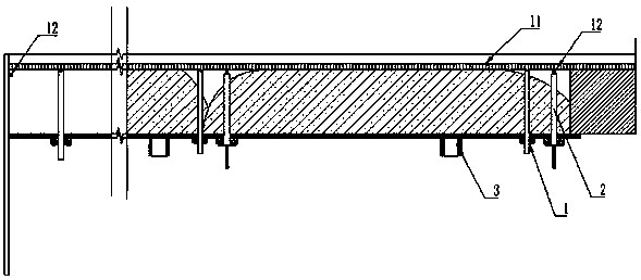
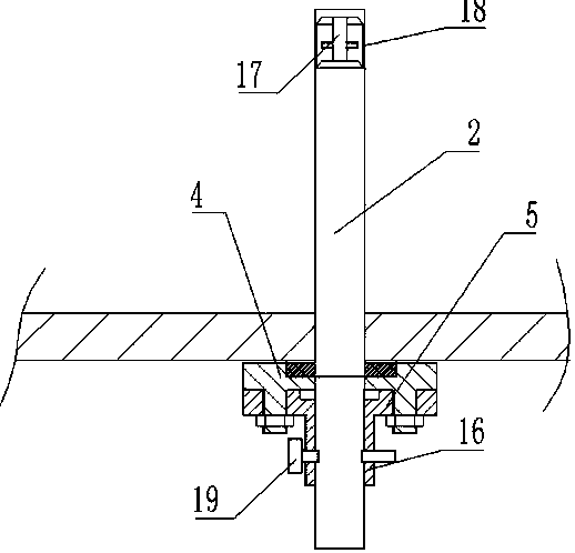
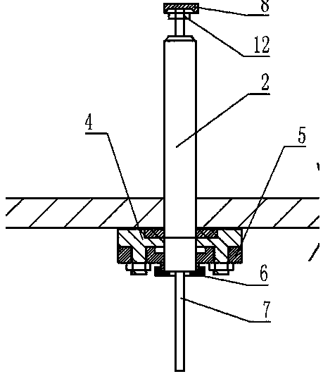
[0031] An observation hole and a grouting hole are provided on the vault formwork of the lining trolley, and a fixed flange 4 is welded below the observation hole and the grouting hole. Bolts are welded on the fixed flange 4, and the positioning flange 5 is connected by bolts. There is a chute on the upper surface of the fixed flange 4, and an inserting plate 10 is set between the chute and the vault formwork. There is a positioning cylinder 6 in the center of the positioning flange 5, and a pin hole is opened on the cylinder wall, and the observation tube 2 is inserted into the positioning cylinder. 16 and stretch into the place near the tunnel waterproof board 11 through the observation hole. Install the grouting pipe 1 in the grouting hole again.
[0032] A section of observation window 18 is arranged at the top of observation tube 2, and observation window 18 is an annular transparent structure, and camera and lighting lamp, stepper motor and column 17 are installed in obs...
Embodiment 2
[0035] First, punch holes in the top form of the lining trolley, except for the second lining filling hole 3 of the vault, drill 3 vault grouting holes and 2 observation holes along the highest longitudinal position of the vault formwork, and 3 vault filling holes The holes are grouting holes, intermediate vent holes (spare grouting holes), and end die vent holes in sequence. Weld fixed flange 4 under the hole, fixed flange 4 upper surface offers chute, and flashboard 10 is installed in the chute, and flashboard 10 center has hole, can slide flashboard 10 to open or close observation hole. The fixed flange 4 is connected to the positioning flange 5 by bolts. One positioning flange 5 is used to install the grouting pipe 1, and the other positioning flange 5 is used to install the observation tube 2. The center of the positioning flange 5 has an observation tube 3 or The installation hole of grouting pipe 1 is used to install bottom cover 6 at the bottom of the installation hole...
Embodiment 3
[0039] Embodiment 3: This embodiment is to transform the existing trolley, and the transformation and construction steps are as follows:
[0040] (1) Mounting flange for the hole in the roof plate of the trolley
[0041]First, punch holes in the top mold of the lining trolley. Except for the second lining perfusion hole 3 of the vault, three vault perfusion holes and two observation holes are drilled along the highest longitudinal position of the vault formwork, and the three vault perfusion holes are sequentially drilled. It is the grouting hole, the middle vent hole (spare grouting hole), and the end die vent hole. Weld the fixed flange 4 under the five holes. The fixed flange 4 is connected to the positioning flange 5 by bolts. One positioning flange 5 is used to install the grouting pipe 1, and the other positioning flange 5 is used to install the observation tube 2. The center of the positioning flange 5 has an observation tube 3 or The mounting hole of the grouting pip...
PUM
 Abstract
Description
Claims
Application Information
 - Generate Ideas
- Intellectual Property
- Life Sciences
- Materials
- Tech Scout
- Unparalleled Data Quality
- Higher Quality Content
- 60% Fewer Hallucinations
Browse by: Latest US Patents, China's latest patents, Technical Efficacy Thesaurus, Application Domain, Technology Topic, Popular Technical Reports.
© 2025 PatSnap. All rights reserved.Legal|Privacy policy|Modern Slavery Act Transparency Statement|Sitemap|About US| Contact US: help@patsnap.com