Cloth cutting machine for garment manufacturing and cutting method thereof

A garment manufacturing and cutting machine technology, which is applied in the field of fabric cutting machines for garment manufacturing, can solve the problems of general safety and easy access to the operator's limbs, and achieve the effects of improving safety, preventing collisions with knives, and stabilizing the structure

Active Publication Date: 2020-08-11
IANGSU COLLEGE OF ENG & TECH
View PDF5 Cites 0 Cited by
  • Summary
  • Abstract
  • Description
  • Claims
  • Application Information

AI Technical Summary

Problems solved by technology

[0003] In the process of garment manufacturing, cutting machines are often used to cut fabrics, but the blades of existing cutting machines are still relatively easy to touch the operator's limbs, and the safety is average.

Method used


Image

  • Cloth cutting machine for garment manufacturing and cutting method thereof
  • Cloth cutting machine for garment manufacturing and cutting method thereof
  • Cloth cutting machine for garment manufacturing and cutting method thereof

Examples


Embodiment 1

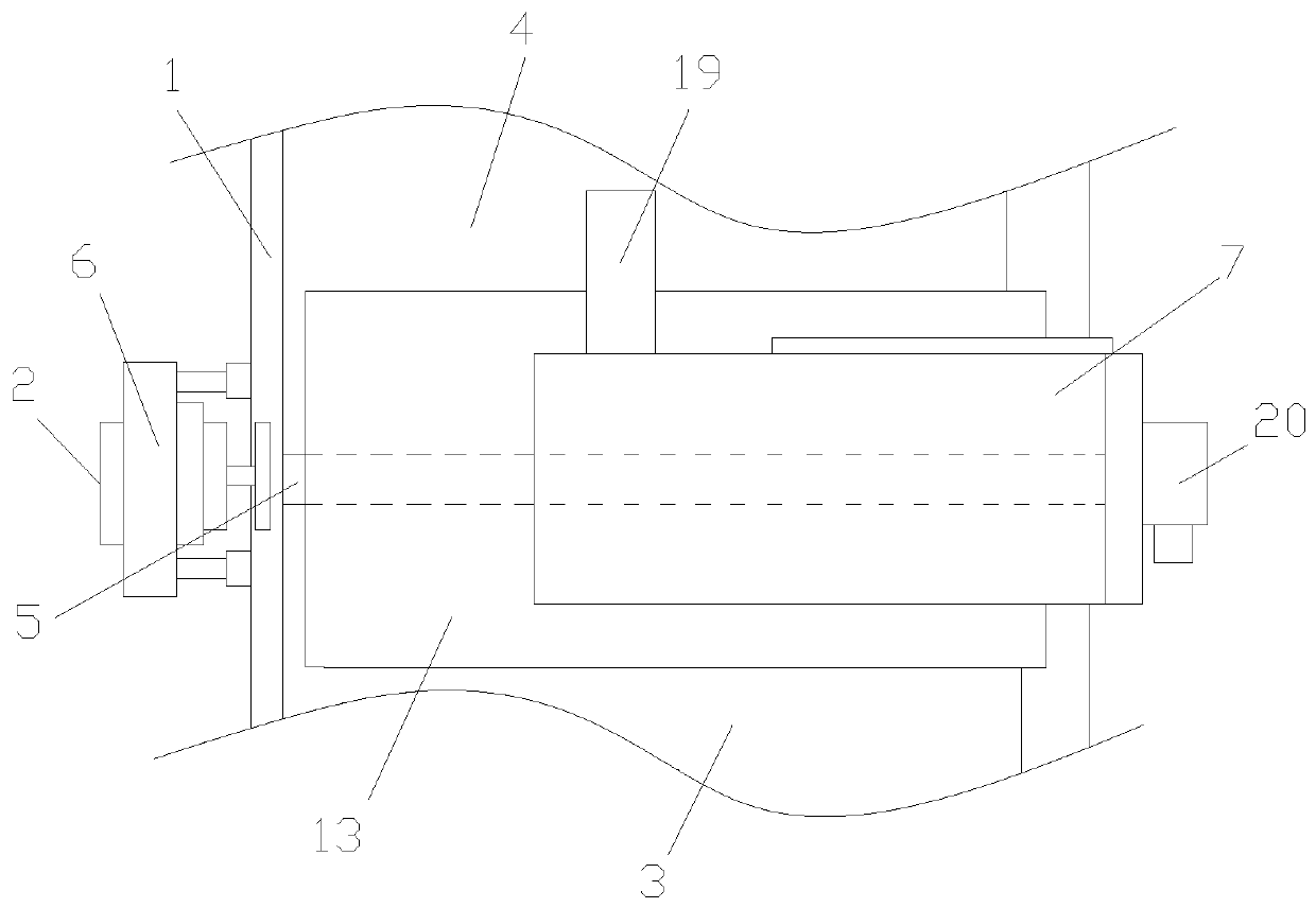
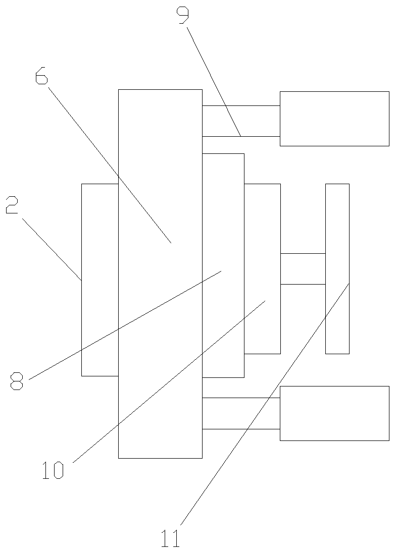
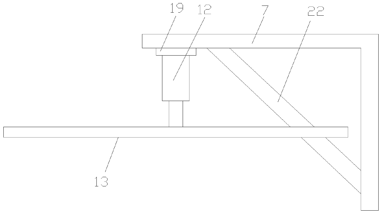
[0030] Such as Figure 1-4As shown, a cloth cutting machine for garment manufacturing includes a cutting table 1, a control device 2, a cutting device, a first conveying mechanism 3 and a second conveying mechanism 4, the control device 2 is a PLC, and the first conveying mechanism 3 and the second conveying mechanism 4 are installed on the cutting table 1, a gap 5 is formed between the first conveying mechanism 3 and the second conveying mechanism 4, the two ends of the gap 5 are respectively provided with first connecting plates 6 and the second connecting plate 7, the inside of the first connecting plate 6 is provided with a first electric guide rail 8 and a first electric push rod 9, an incremental encoder 10 is installed on the slider of the first electric guide rail 8, and the The rotating shaft of the incremental encoder 10 is connected with the measuring wheel 11, the control device 2 is located outside the first connecting plate 6, and the two ends of the first electr...

Embodiment 2

[0033] Such as Figure 1-6 As shown, a cloth cutting machine for garment manufacturing includes a cutting table 1, a control device 2, a cutting device, a first conveying mechanism 3 and a second conveying mechanism 4, the control device 2 is a PLC, and the first conveying mechanism 3 and the second conveying mechanism 4 are installed on the cutting table 1, a gap 5 is formed between the first conveying mechanism 3 and the second conveying mechanism 4, the two ends of the gap 5 are respectively provided with first connecting plates 6 and the second connecting plate 7, the inside of the first connecting plate 6 is provided with a first electric guide rail 8 and a first electric push rod 9, an incremental encoder 10 is installed on the slider of the first electric guide rail 8, and the The rotating shaft of the incremental encoder 10 is connected with a measuring wheel 11, and both the first connecting plate 6 and the measuring wheel 11 are hollow. The first connecting plate 6 ...


PUM


Abstract

The invention discloses a cloth cutting machine for clothing manufacturing, which includes a cutting table, a control device, a cutting device, a first conveying mechanism and a second conveying mechanism, and the first conveying mechanism and the second conveying mechanism are both installed on the cutting table. A gap is formed between the first conveying mechanism and the second conveying mechanism, the two ends of the gap are respectively provided with a first connecting plate and a second connecting plate, and the inside of the first connecting plate is provided with a first electric guide rail and a second connecting plate. An electric push rod, an incremental encoder is installed on the slider of the first electric guide rail, the rotating shaft of the incremental encoder is connected with a measuring wheel, the control device is located on the outside of the first connecting plate, the second Two ends of an electric push rod are respectively fixedly connected with the first connecting plate and the cutting table, the second connecting plate is arranged in an L shape, and a second electric push rod is installed on the second connecting plate, and the second electric push rod A pressing plate is arranged at the end of the rod; the cloth cutting machine for garment manufacturing has good safety.

Description

technical field [0001] The invention relates to the technical field of garment production, in particular to a cloth cutting machine for garment production. Background technique [0002] Cutting machine is an indispensable equipment in some light industries. In the traditional concept, the cutting machine is a machine that uses the force of machine movement to pressurize the die to punch non-metallic materials. It is commonly used in the segmentation and cutting of sheets in various industries. It does not require any molds; it is controlled by the system software, and then directly cuts the product. As long as the corresponding parameters are set on the operating platform, the computer transmits the corresponding instructions. to the cutter. [0003] Cutting machines are often used to cut fabrics in the garment manufacturing process, but the blades of existing cutting machines are still relatively easy to touch the operator's limbs, and the safety is average. Contents of...

Claims


Application Information

Patent Timeline
Patent Type & Authority Patents(China)
IPC IPC(8): D06H7/00
CPCD06H7/00
Inventor 朱晓炜魏振乾丁永青
Owner IANGSU COLLEGE OF ENG & TECH
Why Eureka
Try Eureka