
Automatic positioning, grinding and correcting machining die for hub of electric automobile

An automatic positioning and electric vehicle technology, which is applied in the direction of manufacturing tools, other manufacturing equipment/tools, measuring devices, etc., can solve the problems of hub rotation deviation, hub positioning deviation, and affecting the quality of the hub, etc.

Inactive Publication Date: 2018-06-01
刘秀娟
View PDF0 Cites 18 Cited by
  • Summary
  • Abstract
  • Description
  • Claims
  • Application Information

AI Technical Summary

Problems solved by technology

[0004] In order to solve the above problems, the present invention provides an electric vehicle hub automatic positioning, grinding and correction processing mold, which can solve the problem that the existing structure of the hub cannot be aimed at the hub when the valve hole drilling and flatness detection of the hub of the electric vehicle are performed. There will be deviations in the positioning of the hub during fixation, the fixation of the hub is not firm, there will be deviations when controlling the rotation of the hub, manual grinding of the valve hole, errors in the detection of the tire seat of the hub will affect the quality of the hub and other problems; it can be realized Stable fixation of the wheel hub of electric vehicles, drilling and grinding of the valve hole of the wheel hub, detection and correction of the wheel hub, with the ability to fix the hub according to the structure of the hub, automatic positioning without deviation, fixation of the hub Strong, stable and no deviation when controlling the rotation of the wheel hub, automatic grinding of the valve hole, no error in the detection of the tire seat of the wheel hub, etc.

Method used


Image

  • Automatic positioning, grinding and correcting machining die for hub of electric automobile
  • Automatic positioning, grinding and correcting machining die for hub of electric automobile
  • Automatic positioning, grinding and correcting machining die for hub of electric automobile

Examples


Embodiment Construction

[0038] In order to make the technical means, creative features, goals and effects achieved by the present invention easy to understand, the present invention will be further described below in conjunction with specific illustrations. It should be noted that, in the case of no conflict, the embodiments in the present application and the features in the embodiments can be combined with each other.

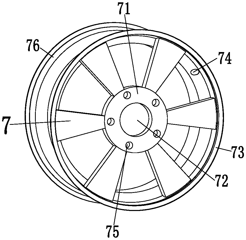
[0039] Such as figure 1 As shown, the existing most common electric vehicle hub 7 includes a bolt disc 71 , a center hole 72 , a rim 73 , a valve hole 74 , a bolt hole 75 and a wheel spoke 76 .

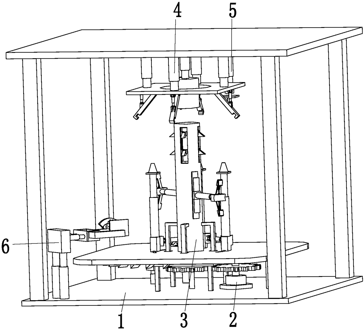
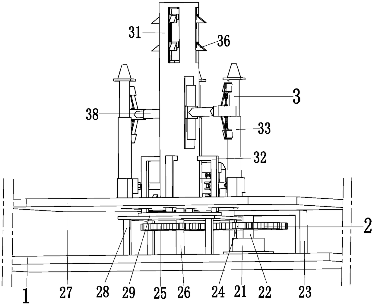
[0040] Such as Figure 2 to Figure 13As shown, an electric vehicle hub automatic positioning, grinding and straightening processing mold includes a supporting base plate 1, a rotating device 2, a fixing device 3, a clamping device 4, a drilling device 5 and a straightening device 6, and the rotating device 2 is installed on On the top of the support base plate 1, a fixing device 3 is insta...


PUM


Abstract

The invention relates to an automatic positioning, grinding and correcting machining die for a hub of an electric automobile. The die comprises a supporting base plate, a rotating device, a fixing device, a clamping device, a drilling device and a correcting device, wherein the rotating device is arranged on the top of the supporting base plate, a fixing device is arranged at the top of the rotating device, the clamping device is connected to the supporting base plate, the drilling device is arranged on the clamping device, and the correcting device is arranged on the left side of the front end of the supporting base plate. According to the die, the problems that when some existing plants carry out valve hole drilling and flatness detecting on the hub of the electric automobile, the quality of a hub is affected due to the facts that the hub cannot be fixed aiming at the structure of the hub, deviation of positioning of the hub can occur, the hub is not fixed firmly, deviation can occurwhen the hub is controlled to rotate, valve holes are ground manually, and errors occur when a tire seat of the hub is detected can be solved.

Description

technical field [0001] The invention relates to the technical field of new energy, in particular to an electric vehicle wheel hub automatic positioning grinding correction processing mold. Background technique [0002] The wheel hub is a metal part that is centrally installed on the transmission shaft and supports the tire. There are many types of wheel hubs on the market. Currently, electric vehicles mainly use aluminum alloy wheels. Aluminum alloy wheels have the advantages of good heat dissipation, light weight, high precision, and more beautiful. There are three manufacturing methods of aluminum alloy wheels, namely, gravity casting, forging, and low-pressure precision casting. Among them, cast wheels account for more than 90%. Hole action, because the tires are basically tubeless tires now, tires with inner tubes are rare, and the tubeless tires are in contact with the hub, so the airtightness of the hub is highly required, as shown in the figure, as figure 1 As shown,...

Claims


Application Information

Patent Timeline
IPC IPC(8): B23P23/04G01B21/20
CPCB23P23/04G01B21/20
Inventor 刘秀娟
Owner 刘秀娟
Learn More