Rotary storage locking mechanism used for furniture
A locking structure and furniture technology, applied in furniture parts, home appliances, applications, etc., can solve the problems of full-length mirror design occupying space, limited storage space in the cabinet, and user injury, so as to improve the effect of horizontal movement to open or close the storage , Horizontal movement to open or close the effect of stable storage and maximized space utilization
- Summary
- Abstract
- Description
- Claims
- Application Information
AI Technical Summary
Problems solved by technology
Method used
Image
Examples
no. 1 example
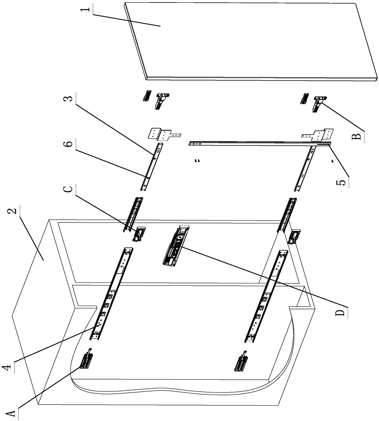
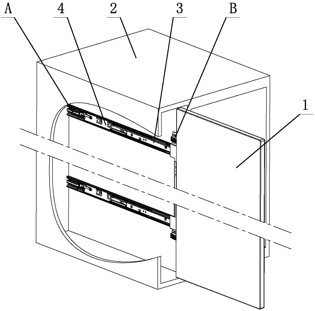
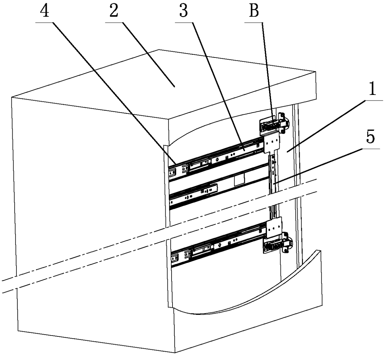
[0043] see Figure 1-Figure 14 , which is used for the rotary storage and locking structure of furniture, including furniture movable parts 1, furniture cabinet body 2 and at least two slide rail assemblies, at least two slide rail assemblies include at least a movable slide rail 3 and a fixed slide rail 4, and the movable slide rail 3 and the fixed slide rail 4 are provided with balls or rollers, and the balls or rollers slide and cooperate with each other, at least two movable slide rails 3 are arranged on the furniture movable part 1, and at least two fixed slide rails 4 are arranged on the furniture cabinet 2, a synchronous rod 5 is arranged between at least two movable slide rails 3, and the synchronous rod 5 slides synchronously on at least two fixed slide rails 4, so as to realize the lateral movement of furniture movable parts 1 and / or close It is stored on the furniture cabinet body 2; among them, a horizontal closing storage device A is arranged between the moving sl...
no. 2 example
[0057] see Figure 15-Figure 17 , the rotary storage locking structure used for furniture, which is different from the first embodiment in that: the horizontal closing and storage device A is arranged on the fixed slide rail 4, and at least includes a locking piece 7 and an elastic piece 9, and the locking piece 7 is movable On the fixed slide rail 4, one end of the elastic member 9 elastically acts on the locking member 7, and the other end elastically acts on the fixed slide rail 4, and the action part 6 is arranged on the movable slide rail 3; the movable slide rail 3 is relatively fixed. When the slide rail 4 moves and closes, it uses the action part 6 to position and drive the locking part 7 to move on the fixed slide rail 4, and the locking part 7 is elastically positioned on the fixed slide rail 4 through the elastic part 9 to lock the movable part 1 of the furniture. Relative to the closed storage position of the furniture cabinet body 2.
[0058] Other unmentioned pa...
no. 3 example
[0060] see Figure 18-Figure 20 , this rotary storage locking structure for furniture is different from the first embodiment in that: the horizontal closing and storage device A is set on the fixed slide rail 4, and at least includes the elastic clamping part 10, and the action part 6 is set on the moving part. On the slide rail 3; when the movable slide rail 3 is closed relative to the fixed slide rail 4, the action part 6 is positioned to act on the elastic clamping part 10 to lock the closed storage position of the furniture movable part 1 relative to the furniture cabinet body 2.
[0061] Other unmentioned parts are the same as the first embodiment.
PUM
 Abstract
Description
Claims
Application Information
 - R&D
- Intellectual Property
- Life Sciences
- Materials
- Tech Scout
- Unparalleled Data Quality
- Higher Quality Content
- 60% Fewer Hallucinations
Browse by: Latest US Patents, China's latest patents, Technical Efficacy Thesaurus, Application Domain, Technology Topic, Popular Technical Reports.
© 2025 PatSnap. All rights reserved.Legal|Privacy policy|Modern Slavery Act Transparency Statement|Sitemap|About US| Contact US: help@patsnap.com


