A substation damping frame

A substation and frame technology, applied in substations, closed substations, substations/power distribution device shells, etc., can solve problems such as installation inconvenience

Active Publication Date: 2019-08-23
SHANGHAI SHENJIE ENVIRONMENTAL PROTECTION TECH DEV
View PDF5 Cites 0 Cited by
  • Summary
  • Abstract
  • Description
  • Claims
  • Application Information

AI Technical Summary

Problems solved by technology

[0003] The purpose of the present invention is to overcome the deficiencies of the existing substation structure, and solve the problem of inconvenient installation for the maintenance operators when integrating the equipment in the substation structure, so as to provide a substation with simple structure, convenient disassembly and assembly, and strong earthquake resistance framework

Method used


Image

  • A substation damping frame
  • A substation damping frame
  • A substation damping frame

Examples


Embodiment Construction

[0021] The present invention will be further described below in conjunction with the accompanying drawings.

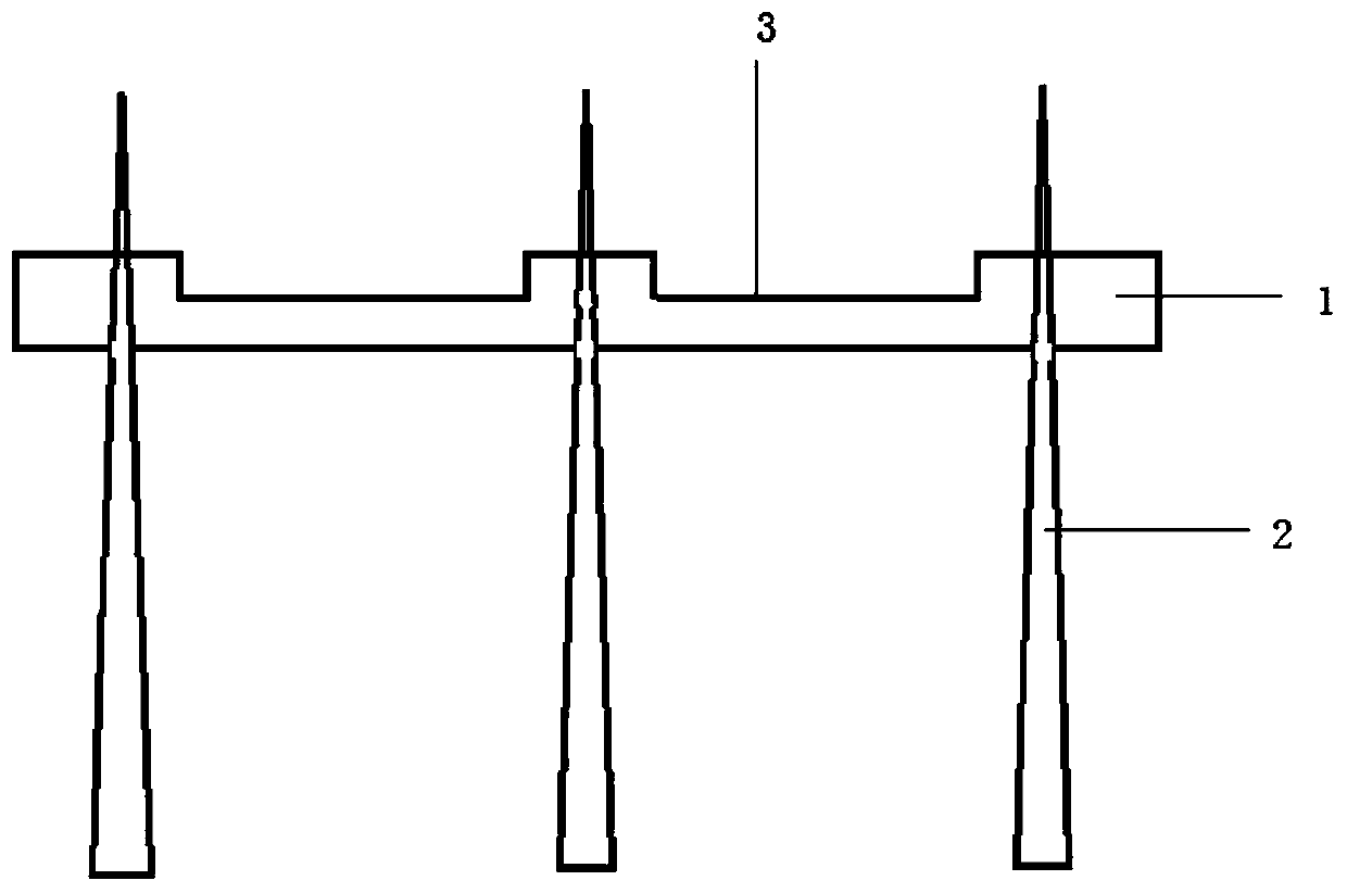
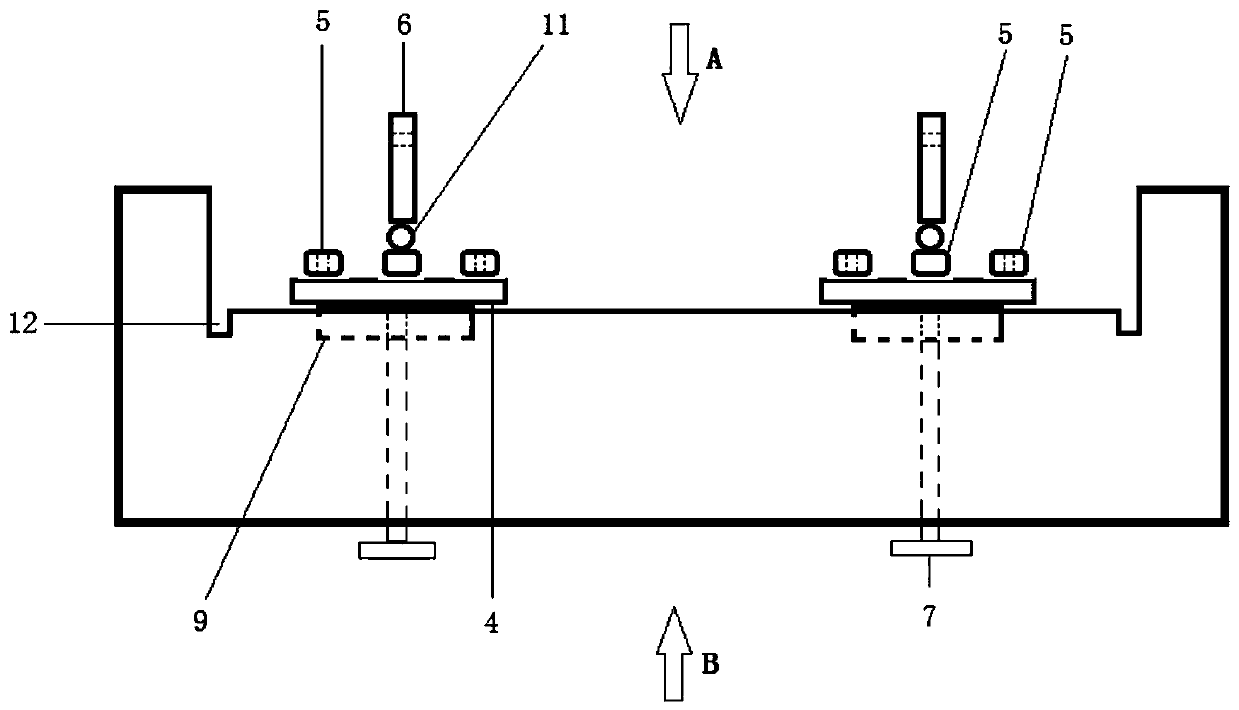
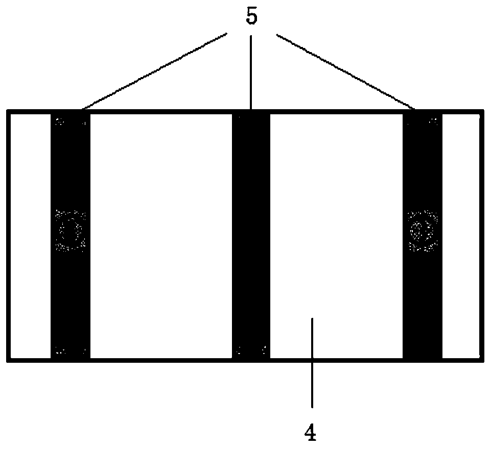
[0022] Such as figure 1 , figure 2 , image 3 , Figure 4 As shown, a substation damping frame includes a beam body 1 and a plurality of support columns 2, the beam body 1 is fixed on a plurality of support columns 2, the beam body 1 is a hollow structure, and is located on adjacent support columns The upper surface of the beam body 1 between 2 is provided with a guide groove 3 along the axial direction of the beam body, and the surface of the guide groove 3 is provided with two slide grooves arranged in parallel along the axial direction of the beam body 1 8. The chute 8 runs through the inside of the beam body 1, and the chute 8 is symmetrically provided with two positioning members that slide and fit, and the two positioning members are adjusted in the distance of the chute 8 for fixing Different sizes of equipment to be fixed.

[0023] The positioning member ...


PUM


Abstract

The invention relates to a damping architecture of a transformer substation. The damping architecture comprises a cross beam body that has a hollow structure and is fixed on a plurality support posts.Guiding slots extending along the axial direction of the cross beam body are formed in the parts, between the adjacent support posts, of the cross beam body; and chutes in parallel to the axial direction of the cross beam body are formed in the surfaces of the guiding slots. Two positioning members in a cooperative sliding manner are arranged at the chutes; each positioning member consists of a bottom plate, a plurality of support blocks, and a rotating member; the rotating member is in rotation connection with the support blocks to realize selection of a vertical position and a parallel position of the rotating member and the cross beam body; and the rotating member is provided with a through hole to fix an electrical device. Besides, sliding lugs matching the chutes are arranged below the bottom plate. And a buffer layer, an insulation layer, and a protection layer are arranged on the lower surface of the bottom plate of each positioning member from inside to outside. Therefore, theinfluence on a to-be-fixed device by vibration caused by operation of primary equipment is eliminated. The architecture has advantages of high expandability, great convenience in disassembling and assembling, and good shock resistance performance.

Description

technical field [0001] The invention relates to the technical field of substation equipment, in particular to a substation damping frame. Background technique [0002] In the field of substation structure, multiple sets of "T" or "π" support beam structures are usually used, and corresponding electrical components are directly fixed on the support beams, usually isolating switches, circuit breakers, transformers, etc. With the rapid development of smart grid, the operation and maintenance of substations is gradually moving towards unmanned and intelligent. Therefore, it is necessary to integrate various intelligent equipment in substations, such as temperature monitoring, icing monitoring, weather monitoring, video monitoring, pollution monitoring and other equipment , while the traditional substation frame is only provided with a fixed structure of the corresponding primary components. For the integration of other secondary equipment on the frame, the operator needs to adju...

Claims


Application Information

Patent Timeline
Patent Type & Authority Patents(China)
IPC IPC(8): H02B1/54H02B7/00H02B1/28
Inventor 陈志军
Owner SHANGHAI SHENJIE ENVIRONMENTAL PROTECTION TECH DEV
Why Eureka
Try Eureka