Condensation water recycling heat-supply system based on water-water ejector

A water-water ejector and heating system technology, which is applied in the heating system, hot water central heating system, household heating and other directions, can solve problems such as the drop of condensate water, increase the return water temperature, reduce the deaerator and High steam extraction, flexible peak shaving and thermo-decoupling effects

Active Publication Date: 2018-05-29
UNI RISING BEIJING TECH CO LTD
View PDF7 Cites 5 Cited by
  • Summary
  • Abstract
  • Description
  • Claims
  • Application Information

AI Technical Summary

Problems solved by technology

Second, when the unit draws steam from the middle row for heating, the amount of steam entering the low-pressure cylinder decreases, and the flow of condensed water will decrease at this time

Method used


Image

  • Condensation water recycling heat-supply system based on water-water ejector
  • Condensation water recycling heat-supply system based on water-water ejector

Examples


Embodiment 1

[0016] Example 1: A power plant has installed two 1000MW direct air cooling units. A single steam turbine provides heat.

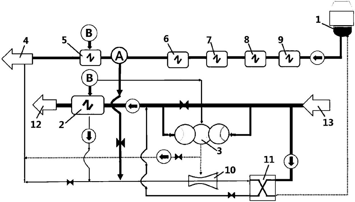
[0017] The hot well of the condenser is connected to the heat recovery system. The heat recovery system includes 9# low-pressure heater, 8# low-pressure heater, 7# low-pressure heater, 6# low-pressure heater, 5# low-pressure heater, and deaerator, connected in series Connection, the 9# low-pressure heater is connected to the condenser hot well; the heat network water supply and return system includes an absorption heat pump and a heat network heater. The return water of the heating network is connected to the input of the heating network heater, and the output provides heated water supply for the heating network. The heat absorption end of the absorption heat pump is connected to part of the return water of the heat network as the heat absorption medium. (not shown in the figure) is used as a heat release medium for recovering the waste heat of exhaust s...

Embodiment 2

[0038] Embodiment 2: similar to embodiment 1,

[0039] A power plant installed two 1000MW direct air cooling units. A single steam turbine provides heat.

[0040]The hot well of the condenser is connected to the heat recovery system, and the heat recovery system includes 9# low pressure heater, 8# low pressure heater, 7# low pressure heater, 6# low pressure heater, 5# low pressure heater, deaerator, connected in series Connection, the 9# low-pressure heater is connected to the hot well of the condenser; the heating network supply and return water system includes the heating network heater. The return water of the heating network is connected to the input of the heating network heater, and the output provides heated water supply for the heating network.

[0041] First, high temperature hydrophobic.

[0042] The heating steam of the heat network heater comes from the five-stage extraction steam B or the middle exhaust steam.

[0043] Part of the five-stage extraction steam i...


PUM


Abstract

The invention provides a condensation water recycling heat-supply system based on a water-water ejector. The condensation water recycling heat-supply system comprises a condenser heat well, a heat regenerative system, a heat supply network water supply and backwater system, the water-water ejector and a plate heat exchanger, wherein the heat supply network water supply and backwater system comprises an absorption heat pump and a heat supply network heater, a water drainage pipeline of the heat supply network heater is connected with a power water inlet of the water-water ejector, a water drainage pipeline of the absorption heat pump is connected with a pump suction port of the water-water ejector, a water outlet of the water-water ejector is connected with a heat release side inlet of theplate heat exchanger, and a heat release side outlet of the plate heat exchanger is connected with the condenser heat well; and heat supply network backwater is connected to a heat absorption side inlet of the plate heat exchanger through a heat supply network backwater branch pipe, and a heat absorption side outlet of the plate exchanger is connected to a water inlet pipeline of the heat supply network heater. Heat of high-temperature water draining and heat of high-temperature water condensation are recycled, and energy-conservation emission reduction and thermoelectric decoupling of a wholethermal power plant are promoted.

Description

technical field [0001] The invention belongs to the field of energy saving of power plants and relates to a condensed water recirculation heating system based on water jets. Background technique [0002] Under the two operating conditions of thermal power plants, the amount of condensed water in the recuperation system will decrease. First, when the unit draws steam from the middle row for heating, the amount of steam entering the low-pressure cylinder of the steam turbine decreases, and the flow rate of condensed water also decreases accordingly. Second, connect the exhaust steam (exhaust steam) of the low-pressure cylinder to the absorption heat pump to recover the waste heat of the exhaust steam. The amount of exhaust steam entering the condenser or the air cooling island is greatly reduced, and the flow rate of condensed water is also greatly reduced. [0003] There are currently two problems. First, when the unit is running with steam extraction, a considerable part o...

Claims


Application Information

Patent Timeline
Patent Type & Authority Applications(China)
IPC IPC(8): F24D3/10F28C3/06F28B9/08
CPCF24D3/10F28B9/08F28C3/06
Inventor 介智华
Owner UNI RISING BEIJING TECH CO LTD
Why Eureka
Try Eureka