Camera mounting structure and display equipment

A technology of installation structure and camera, applied in mechanical equipment, image communication, TV and other directions, can solve the problems of camera being prone to jam, restricting the structure and appearance design of display equipment, etc., to achieve the effect of no jam and smooth movement.

Active Publication Date: 2018-05-29
SHENZHEN SKYWORTH RGB ELECTRONICS CO LTD
View PDF7 Cites 6 Cited by
  • Summary
  • Abstract
  • Description
  • Claims
  • Application Information

AI Technical Summary

Problems solved by technology

However, with this structure, the camera is prone to freeze during the sliding process, and it limits the structure and appearance design of the display device.

Method used


Image

  • Camera mounting structure and display equipment
  • Camera mounting structure and display equipment
  • Camera mounting structure and display equipment

Examples


Embodiment Construction

[0044] In order to make the technical problems solved by the present invention, the technical solutions adopted and the technical effects achieved clearer, the technical solutions of the present invention will be further described below in conjunction with the accompanying drawings and through specific implementation methods.

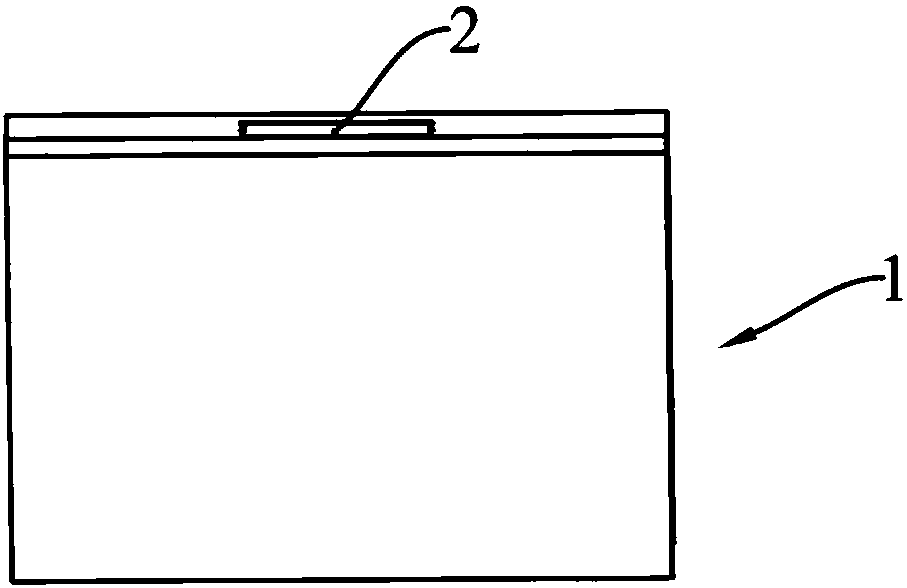
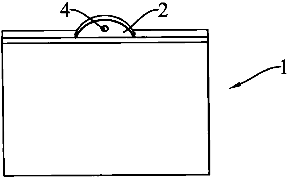
[0045] Such as Figure 1-Figure 11 As shown, this embodiment provides a display device, including a display panel 11 and a camera installation structure, and the display device may be a TV, a display screen, and the like. Since the camera function is not a common function of the display device, in order to improve the integrity and aesthetics of the display device, such as figure 1 and figure 2 As shown, the camera can be hidden inside the display device when not in use, and protrude from the top of the display device by rotating it when in use.

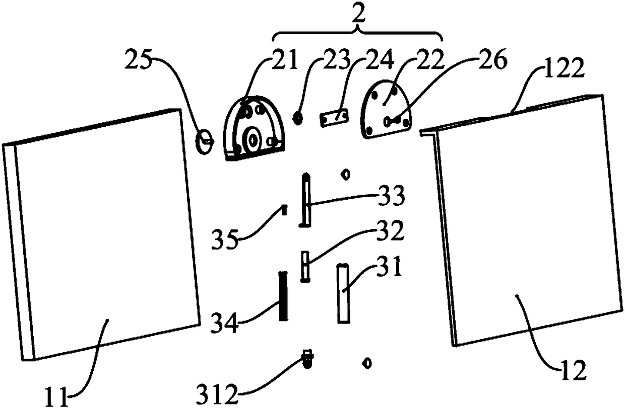
[0046] Such as image 3 and Figure 4 As shown, the camera installation structure includes a housing 1...


PUM


Abstract

The invention discloses a camera mounting structure and display equipment. The camera mounting structure comprises a shell body, a mounting block and a telescoping rod; a containing space is formed inthe shell body in a hollow manner and an opening which communicates with the containing space is arranged at the shell body; the mounting block is located in the containing space and rotationally connected with the inner wall of the shell body; a camera is arranged on the mounting block; the camera and the rotation center of the mounting block are correspondingly located at the two opposite endsof the mounting block; the telescoping rod is located in the containing space; one end of the telescoping rod is rotationally connected with the inner wall of the shell body and the other end of the telescoping rod is rotationally connected with the mounting block and arranged eccentrically to the rotation center; when the mounting block rotates and enables the telescoping rod to be located at a first position, the mounting block does not bulge out of the shell body; when the mounting block rotates and enables the telescoping rod to be located at a second position, the camera extends out of the opening. According to the camera mounting structure, it can be realized by rotating the mounting block that the camera is hidden or rotated out, and the movement is smooth without stuttering.

Description

technical field [0001] The present invention relates to the technical field of display devices, in particular to a camera mounting structure and a display device. Background technique [0002] Display devices, such as computers, televisions, monitors, etc., all have a camera function, and generally the camera is arranged at the upper end of the front of the display device. Since the camera function is not a common function of the display device, the camera is always exposed outside the display device, which affects the overall appearance of the display device. [0003] In the prior art, there is a display device on which the camera can slide in the display device. When the camera function is not used, the camera is slid into the display device to hide it. When the camera function is used, the camera is slid out of the display device. In this way, the camera is prevented from being exposed to the outside of the display device and is bumped and damaged, and the aesthetic appe...

Claims


Application Information

Patent Timeline
Patent Type & Authority Applications(China)
IPC IPC(8): F16M11/10F16M11/16H04N5/225
CPCF16M11/10F16M11/16H04N23/50
Inventor 胡灵超陈伟雄郭玉宝
Owner SHENZHEN SKYWORTH RGB ELECTRONICS CO LTD
Why Eureka
Try Eureka