Controllable two-stage-ejection vehicle-mounted control system of unmanned aerial vehicle and ejection method

A vehicle-mounted control system and unmanned aerial vehicle technology, applied in the direction of launching/dragging transmission devices, etc., can solve the problems of large longitudinal overload of the wing, excessive initial overload, and reduced initial ejection acceleration, so as to achieve simple control methods and avoid The initial overload is too large and the effect of reducing the initial ejection acceleration

Active Publication Date: 2018-05-29
沈观清
View PDF7 Cites 5 Cited by
  • Summary
  • Abstract
  • Description
  • Claims
  • Application Information

AI Technical Summary

Problems solved by technology

[0021] Aiming at the deficiencies in the prior art, the present invention proposes a controllable two-stage ejection vehicle control system and ejection method for unmanned aerial vehicles, the purpose of which is to reduce the initial ejection acceleration and avoid the problem of excessive initial overload during the ejection process, and at the same time It can also meet the requirement of sufficient off-frame speed, and solve the very dangerous problem in the prior art caused by too much longitudinal overload on the wing during ejection.

Method used

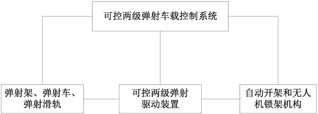
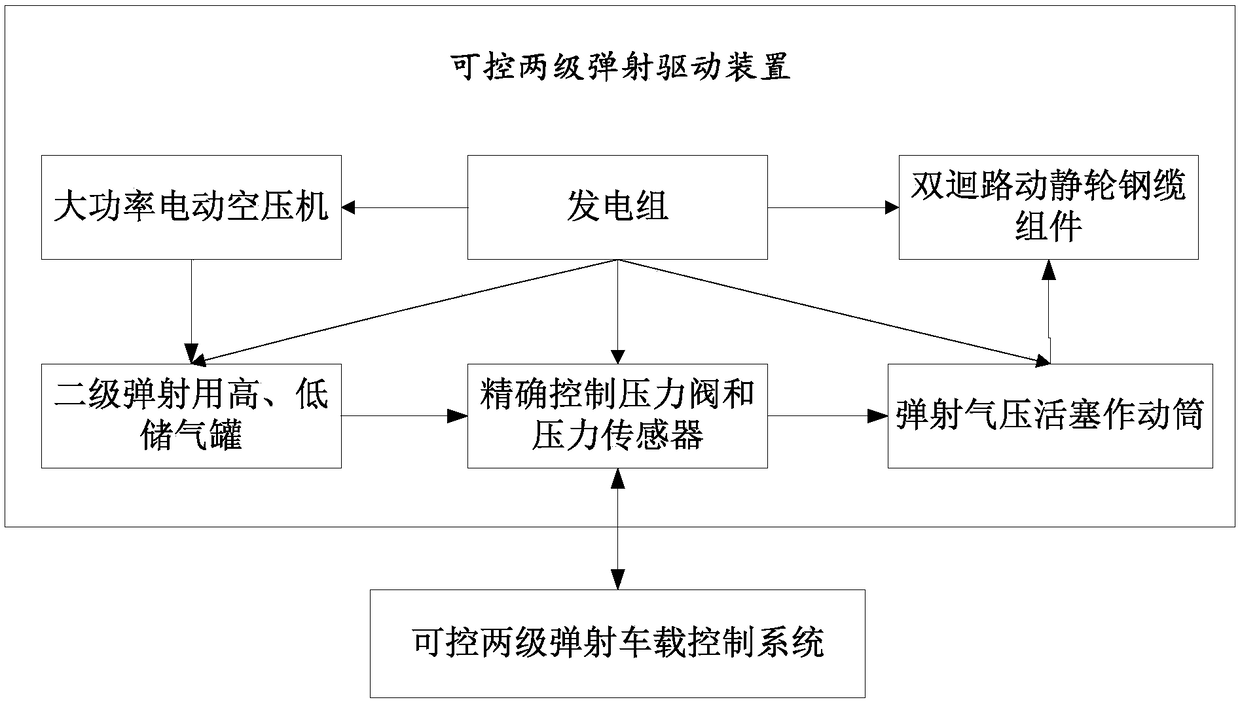
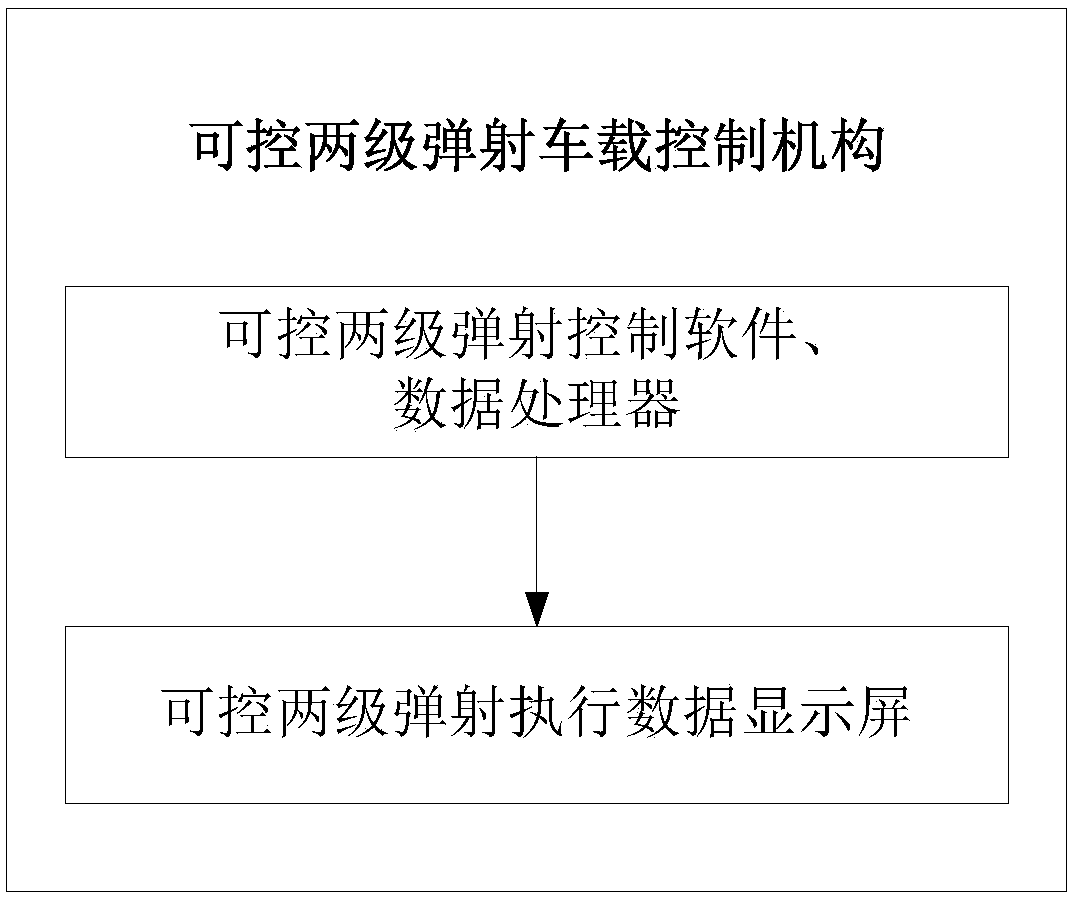

Image

  • Controllable two-stage-ejection vehicle-mounted control system of unmanned aerial vehicle and ejection method
  • Controllable two-stage-ejection vehicle-mounted control system of unmanned aerial vehicle and ejection method
  • Controllable two-stage-ejection vehicle-mounted control system of unmanned aerial vehicle and ejection method

Examples


Embodiment Construction

[0060] The content of the present invention will be further explained below in conjunction with the accompanying drawings.

[0061] 1. Summary of invention principle and invention method:

[0062] 1. The initial overload of the aircraft ejection is too large because the acceleration at the moment of initial ejection is too large, and the acceleration is proportional to the overload coefficient. There are two reasons for the excessive acceleration at the initial ejection moment. First, to make the aircraft generate sufficient departure velocity when it leaves the aircraft, sufficient acceleration must be used in the ejection process to generate sufficient departure velocity. The acceleration is called It is called "ejection acceleration"; secondly, the current three conventional power systems are all overloaded during the initial ejection, that is, the starting point acceleration is the largest, especially for rubber band catapults and rocket catapults, because the starting poi...


PUM


Abstract

The invention discloses a controllable two-stage-ejection vehicle-mounted control system of an unmanned aerial vehicle (UAV). The controllable two-stage-ejection vehicle-mounted control system comprises an ejection frame, an ejection vehicle, an ejection sliding rail, a controllable two-stage-ejection drive mechanism, a controllable two-stage-ejection vehicle-mounted control mechanism, an automatic opening frame and a UAV lock frame mechanism. The invention also discloses a control method of the controllable two-stage-ejection vehicle-mounted control system of the UAV. The control method comprises the steps of respectively generating high-pressure gas and low-pressure gas by an air compressor, sending the high-pressure gas and the low-pressure gas to a high-pressure gas container and a low-pressure gas container, activating first-stage movement of the ejection frame by the controllable two-stage-ejection vehicle-mounted control system while sending a time instruction for activating second-stage movement of the ejection frame to an ejection time relay and a time instruction for releasing an ejection lock fastener, and activating the second-stage movement of the ejection frame and releasing the ejection lock fastener by the ejection time relay. The controllable two-stage-ejection vehicle-mounted control system of the UAV realizes the reduction of initial ejection acceleration, soas to furthest avoid the problem of excessive initial overload during the ejection process and to meet the requirements of enough off-frame speed at the same time.

Description

technical field [0001] The invention belongs to the technical field of unmanned aerial vehicle ejection, and in particular relates to a vehicle-mounted control system and an ejection method for a controllable two-stage ejection of an unmanned aerial vehicle. Background technique [0002] All aircraft that adopt the fixed-wing method need to use the speed of the relative air to generate power to fly. So fixed-wing aircraft usually need to have enough runway to gain enough lift to lift off the ground and into the air when the aircraft reaches a certain speed. An aircraft that also utilizes speed to obtain aerodynamic lift also needs a runway of sufficient length when landing on the ground. Although many aircraft adopt multiple methods to reduce the landing speed to shorten the required runway length when landing, the landing runway cannot be cancelled. [0003] At present, the runway of aircraft can have various paving surfaces of different qualities. For the runway surface ...

Claims


Application Information

Patent Timeline
Patent Type & Authority Applications(China)
IPC IPC(8): B64F1/06
CPCB64F1/06
Inventor 沈观清
Owner 沈观清
Why Eureka
Try Eureka