
Acquisition method and device of coding starting point

An acquisition method and acquisition device technology, which are applied in image communication, digital video signal modification, electrical components, etc., can solve problems such as affecting code rate, image quality degradation, and increasing search calculation, and achieve the basic goal of avoiding search and reducing video code rate. The effect of unchanged, maintaining image quality

Active Publication Date: 2018-05-25
ALIBABA GRP HLDG LTD
View PDF5 Cites 13 Cited by
  • Summary
  • Abstract
  • Description
  • Claims
  • Application Information

AI Technical Summary

Problems solved by technology

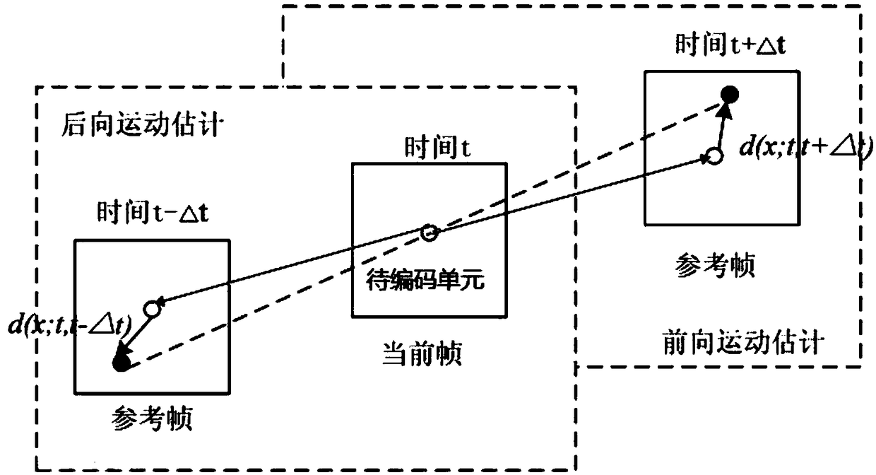
[0005] It can be seen that under the existing motion estimation scheme, in the reference frame, the point at the same position of the coding block in the current PU is the center, that is, the starting point, and the motion search is performed; the actual motion situation is not considered, and the adjacent frames The movement between will cause the position of the matching block to change. If the same position of the coding block in the current PU in the reference frame is still selected as the starting point, the position of the starting point will be far away from the matching block, which will lead to finding the best Computational increase for best matching blocks
Furthermore, using a fixed motion search range for all blocks in the same target image, if the search range is large enough to capture the fastest moving object in the image, then this unnecessarily increases the The search and calculation of the area leads to a huge amount of calculation, waste of computing resources, and reduce computing efficiency
On the contrary, if the search range is too small, because the reference block may be outside the search range, the motion estimation method may not be able to find a reference block with a large amount of movement, and cannot find the best matching block, which will affect The encoded image quality and the encoded bit rate make the image quality decrease and the encoded bit rate increase

Method used


Image

  • Acquisition method and device of coding starting point
  • Acquisition method and device of coding starting point
  • Acquisition method and device of coding starting point

Examples


Embodiment Construction

[0085] In order to better understand the above-mentioned purpose, features and advantages of the present application, the present application will be further described in detail below in conjunction with the accompanying drawings and specific embodiments. It should be noted that, in the case of no conflict, the embodiments of the present application and the features in the embodiments can be combined with each other.

[0086] In the following description, numerous specific details are set forth in order to provide a thorough understanding of the application. However, the present application can be implemented in many other ways different from those described here, and those skilled in the art can make similar promotions without violating the connotation of the present application. Therefore, the present application is not limited by the specific implementations disclosed below.

[0087] Before describing the specific steps of this embodiment in detail, in order to facilitate t...


PUM


Abstract

The application discloses an acquisition method of a coding starting point and an acquisition device of the coding starting point. The acquisition method of the coding starting point comprises the following steps: acquiring a motion vector of a prediction unit; acquiring location information of a to-be-coded unit in the current frame; acquiring a location same as the location information of the to-be-coded unit in a first reference frame corresponding to the to-be-coded unit; and performing offset on the location according to the motion vector, and determining the starting point of the to-be-coded unit in the reference frame. Through the technical scheme disclosed by the application, a motion estimation starting point is set according to actual motion situation through the existing motionvector, the starting point is closer to the real motion vector, the fixed motion search range can be shrunk, the real motion vector can be found by performing small-scale searching by taking the starting point as a center, so that the image quality and the video code rate can be maintained unchanged basically, the searching in an overall big window is avoided, the searching process is reduced, andthe time for motion estimation is reduced, thereby reducing the coding time and improving the coding efficiency.

Description

technical field [0001] The present application relates to the technical field of video coding, and in particular to a method for obtaining a coding starting point and a device for obtaining a coding starting point. Background technique [0002] Currently, in the process of video coding, the intra-frame prediction method is usually used to eliminate the spatial redundancy of the image, and the inter-frame prediction method is used to eliminate the temporal redundancy. Since the temporal redundancy between adjacent frames of a video source is much larger than the spatial redundancy within a frame, this makes the inter-frame prediction method extremely important in video coding. Because the video sequence images have a strong correlation on the time axis, motion estimation and motion compensation techniques in inter-frame prediction can effectively reduce time redundancy, so this technology is widely used in video compression coding schemes. [0003] Motion estimation is used ...

Claims


Application Information

Patent Timeline
IPC IPC(8): H04N19/513H04N19/57H04N19/172H04N19/159
CPCH04N19/159H04N19/172H04N19/513H04N19/57
Inventor 沈操江文斐储开颜
Owner ALIBABA GRP HLDG LTD
Learn More