
A built-in alternating pole permanent magnet motor based on rotor complementary structure

A technology of permanent magnet motor and alternating poles, which is applied in the shape/style/structure of the magnetic circuit, the shape/style/structure of the winding conductor, the magnetic circuit, etc., and can solve the asymmetry and torque ripple of the magnetic circuit with different polarity and alternating poles Excessive size, complex motor structure, etc., achieve the effect of saving permanent magnet materials, maintaining a balance between positive and negative amplitudes, and reducing the difficulty of manufacturing processes

Active Publication Date: 2020-06-30
SOUTHEAST UNIV
View PDF13 Cites 0 Cited by
  • Summary
  • Abstract
  • Description
  • Claims
  • Application Information

AI Technical Summary

Problems solved by technology

[0004] Technical problem: In view of the above existing problems and the prior art, the present invention proposes a built-in alternating pole permanent magnet motor based on the complementary structure of the rotor, which solves the problem of excessive torque ripple of the traditional permanent magnet motor and the problem of different polarity alternating pole magnetic circuits. Asymmetry, the problem of complex motor structure

Method used


Image

  • A built-in alternating pole permanent magnet motor based on rotor complementary structure
  • A built-in alternating pole permanent magnet motor based on rotor complementary structure
  • A built-in alternating pole permanent magnet motor based on rotor complementary structure

Examples


Embodiment Construction

[0025] The present invention will be specifically described below according to the accompanying drawings:

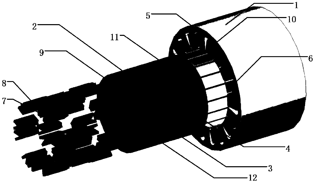
[0026] like figure 1 As shown, it is a built-in alternating pole permanent magnet motor based on the complementary rotor structure, including a stator 1, a first rotor 2, a second rotor 3, a third rotor 4, armature teeth 5, fault-tolerant teeth 6, S permanent Magnetic pole 7 , N permanent magnet pole 8 , iron core pole 9 , armature winding 10 , first magnetic isolation sheet 11 and second magnetic isolation sheet 12 .

[0027] by the following formula

[0028]

[0029] Set the number of pole pairs P of the first rotor 2, the second rotor 3, and the third rotor 4 r If both are 9, it can be deduced that the number of stator slots S is 20. Among them, a is a constant (usually the value is 1), and b is the number of motor phases 5. The armature teeth 5 and the fault-tolerant teeth 6 are arranged alternately in turn to improve the self-inductance of the motor and reduc...


PUM


Abstract

The invention discloses a built-in alternative-pole permanent-magnet motor based on a rotor complementary structure. In the motor, a permanent magnet pole S (7), a permanent magnet pole N (8) and an iron core pole (9) are respectively disposed in a first rotor (2), a second rotor (3) and a third rotor (4) in a heteropolar alternative-pole mode. The three-rotor structure is nested in a stator (1),and is coaxial with the stator (1). The stator (1) comprises armature teeth (5) and fault-tolerant teeth (6), wherein the armature teeth (5) and fault-tolerant teeth (6) are alternately arranged alongthe periphery of the stator (1). The armature teeth (5) is provided with an armature winding (10), and the armature winding (10) is wound in a mode of single-layer fractional-slot centralized winding. Compared with a multi-stator structure and a distributed winding, the alternative-pole rotor complementary structure is simple and reliable, is low in cost, has no magnetic circuit coupling, is small in copper loss, and is high in efficiency. Because the stator (1) is just provided with one single-layer fractional-slot centralized winding, a motor end part is small in loss, and the torque and power density are high.

Description

technical field [0001] The invention belongs to the structural design of a motor, and in particular relates to a built-in alternating pole permanent magnet motor based on a rotor complementary structure. Background technique [0002] Permanent magnet motors have received extensive attention and applications due to their high unit torque and power density. Due to the huge reserves of rare earth resources in my country, accounting for 80% of the world's total rare earth reserves, my country's permanent magnet motor industry has been vigorously developed in the last century. According to the electromagnetic torque T em =p[ψ f i q +(L d -L q )i d i q ] It can be seen that the output torque of the permanent magnet motor can be divided into two parts, that is, the first term, the permanent magnet torque T f and the second term is the reluctance torque T formed by the asymmetry of the rotor magnetic circuit r . It can be seen that the output of the motor mainly comes from...

Claims


Application Information

Patent Timeline
Patent Type & Authority Patents(China)
IPC IPC(8): H02K1/27H02K1/14H02K3/28
CPCH02K1/146H02K1/2753H02K3/28H02K2201/03
Inventor 樊英瞿广宇
Owner SOUTHEAST UNIV
Learn More