Eureka AIR delivers breakthrough ideas for toughest innovation challenges, trusted by R&D personnel around the world.

Bracket device of slide rail

A bracket device and slide rail technology, which can be used in furniture parts, household appliances, drawers, etc., and can solve the problems of design improvement

Active Publication Date: 2018-05-25
KING SLIDE WORKS CO LTD +1
View PDF6 Cites 4 Cited by
  • Summary
  • Abstract
  • Description
  • Claims
  • Application Information

AI Technical Summary

Problems solved by technology

[0004] It is obvious that the design of the previous case still needs to be improved

Method used


Image

  • Bracket device of slide rail
  • Bracket device of slide rail
  • Bracket device of slide rail

Examples


Embodiment Construction

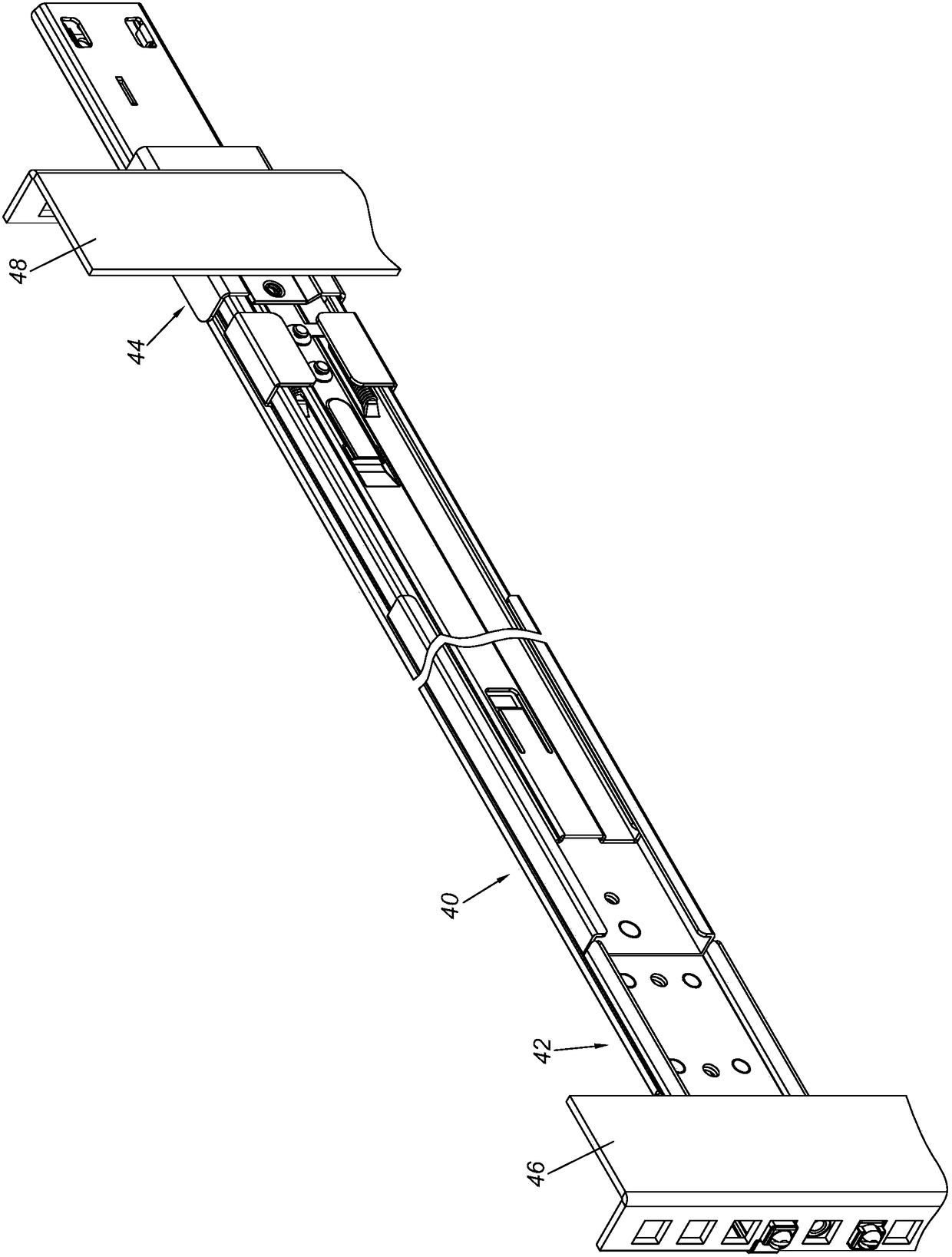
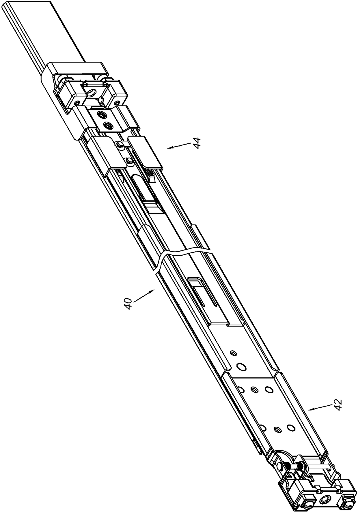
[0057] figure 1 A slide rail assembly 40 showing a first embodiment of the present invention is mounted to a first column 46 and a second column 48 of a rack by means of a first bracket 42 and a bracket device 44 .

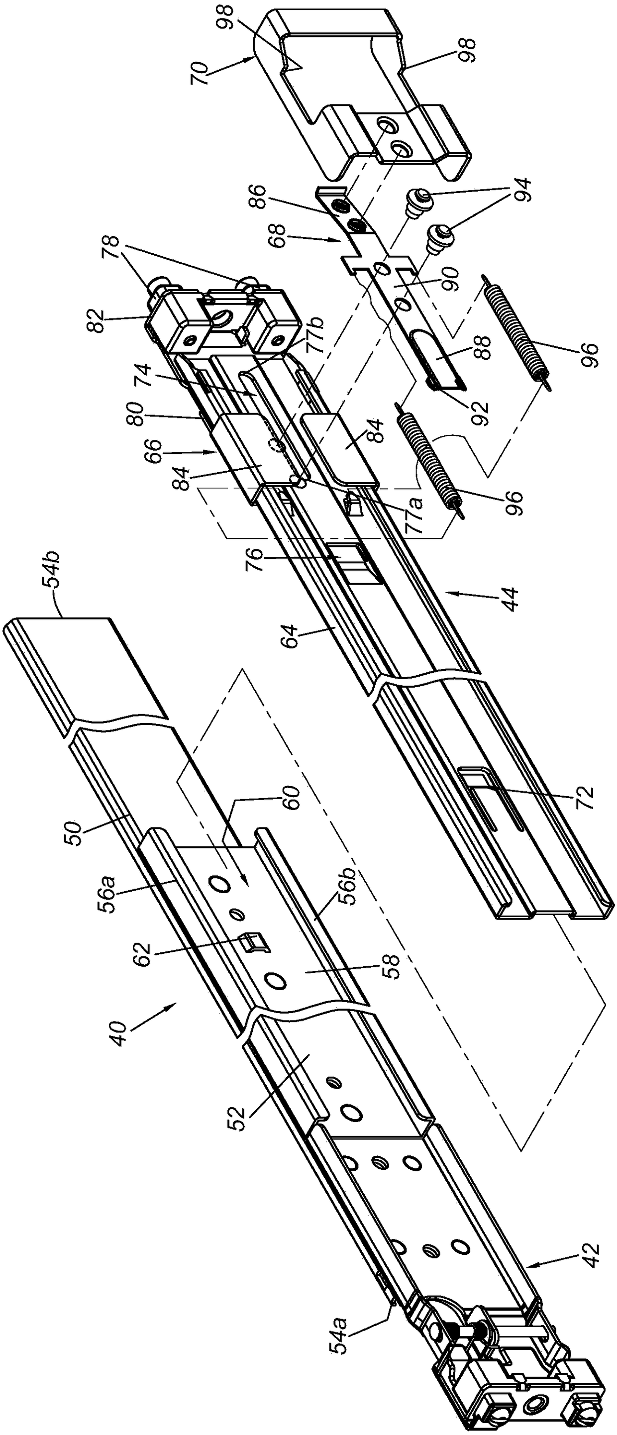
[0058] Such as figure 2 and image 3 As shown, the slide rail assembly 40 includes a rail member 50 and a support rail 52 . The rail member 50 has a first end portion 54 a and a second end portion 54 b opposite to the first end portion 54 a. The support rail 52 is fixedly connected to the back plate of the rail 50 and can be regarded as a part of the rail 50 . The support rail 52 has an upper wall 56a, a lower wall 56b, and a longitudinal wall 58 connected between the upper wall 56a and the lower wall 56b. The upper wall 56 a , the lower wall 56 b and the longitudinal wall 58 jointly define a channel 60 . The first bracket 42 is connected to a first end 54 a adjacent to the rail 50 . Preferably, the longitudinal wall 58 of the support rail 52 is located in ...


PUM


Abstract

The invention relates to a bracket device of a slide rail. The bracket device comprises a supporting frame, a bracket, an elastic part and a buckling part. The bracket is movably connected with the supporting frame. The elastic part is installed on the supporting frame. The buckling part is connected with the elastic part. When the bracket is at a first position relative to the supporting frame, the buckling part is in the locked state, and when the bracket is at a second position relative to the supporting frame, the buckling part is in the unlocked state.

Description

technical field [0001] The invention relates to a bracket device of a slide rail, in particular to a bracket device capable of providing a slide rail mounted to a machine column of a rack. Background technique [0002] Chinese utility model patent announcement number CN205548022U discloses a front-end unlocking rear lock structure for a slide rail, including a slide rail, and a front lock mechanism and a rear lock mechanism are respectively installed at both ends. The structure of the rear lock mechanism is: including a split main board, a main board The main board is respectively the first main board and the second main board. The structure of the first main board is as follows: the first main board body is composed of a "Z" shaped structure in section, and there are a plurality of first main boards in the middle of the first main board Mounting holes, a dovetail bump is provided in the middle of the front end; the structure of the second main board is as follows: the secon...

Claims


Application Information

Patent Timeline
IPC IPC(8): A47B88/90A47B88/40A47B88/50
CPCA47B2210/0029
Inventor 陈庚金杨顺和游凯文王俊强
Owner KING SLIDE WORKS CO LTD
Why Eureka
Eureka Blog
Learn More