
Power-driven tightening type cable sample clamping mechanism and insulating layer peeling equipment

A clamping mechanism and tensioning technology, which is applied in the dismantling/armoring cable equipment, cable installation, cable installation device, etc., can solve the problems of time-consuming and labor-intensive, affecting the efficiency of the cable, and the inability to cut the insulation layer, etc., to achieve saving Human resources, improving accuracy and efficiency, and ensuring quality effects

Pending Publication Date: 2018-05-22
UNIV OF JINAN
View PDF0 Cites 3 Cited by
  • Summary
  • Abstract
  • Description
  • Claims
  • Application Information

AI Technical Summary

Problems solved by technology

In the prior art, the peeling and removal of the insulation layer at both ends of the cable sample mainly relies on manual operation, which is time-consuming and laborious, which affects the efficiency of cable detection, and is also easy to damage the cable core, affecting the accuracy of the test results.
[0003] In order to be able to automatically strip the insulation layer of the cable sample, the cable sample needs to be clamped and tightened so as to perform operations such as cutting the insulation layer. However, various clamping devices in the prior art are not suitable for this Occasions, because on the one hand, it lacks a suitable tensioning device, on the other hand, when clamping the end of the cable sample, it often leads to the inability to cut the insulation layer at the end of the cable sample

Method used


Image

  • Power-driven tightening type cable sample clamping mechanism and insulating layer peeling equipment
  • Power-driven tightening type cable sample clamping mechanism and insulating layer peeling equipment
  • Power-driven tightening type cable sample clamping mechanism and insulating layer peeling equipment

Examples


Embodiment Construction

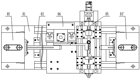
[0052] What should be explained at first is that in the context of the present invention, terms related to orientation such as "left end", "right end", "above" and "below" are used, and these terms are all based on the insulation layer peeled off of the cable sample. The direction of the front view of the equipment is used as the reference, while "axial" and "radial" are based on the axial and radial directions of the cable sample. In addition, each component is described as it is installed on the cable sample insulation stripping equipment, so the viewing directions of "left view", "right view" and "top view" are the same as those of the cable sample Corresponding view directions for insulation stripping equipment.

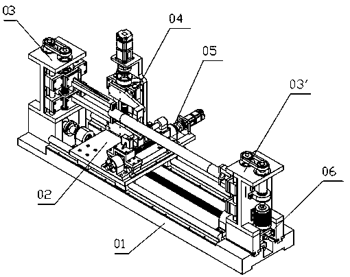
[0053] The following will refer to Figure 1-19 A preferred embodiment of an electric tensioning cable sample clamping mechanism and the corresponding cable sample insulation stripping equipment of the present invention will be described in detail.

[0054] In ...


PUM


Abstract

The invention discloses a power-driven tightening type cable sample clamping mechanism and insulating layer peeling equipment. The power-driven tightening type cable sample clamping mechanism comprises a clamping device and a tightening device, wherein the clamping device comprises a pair of clamping arms and a clamping drive mechanism, a clamping V-type block is arranged at the free end of each clamping arm for clamping the outer surface of a cable sample, the pair of clamping arms synchronously move in a direction of moving towards each other or far away from each other under the drive of the clamping drive mechanism, to achieve center-aligned clamping; the tightening device comprises a fixed part and a movable part, the clamping device is installed on the movable part, the movable partcan slide relative to the fixed part, a power-driven force application device is also arranged between the fixed part and the movable part, for applying a tightening force to the movable part. According to the a power-driven tightening type cable sample clamping mechanism provided by the invention, the cable sample can be conveniently clamped and tightened.

Description

technical field [0001] The invention relates to an electric tensioning type cable sample clamping device and a cable sample insulating layer stripping device provided with it, belonging to the technical field of cable preparation and detection. Background technique [0002] The role of cables in power transmission and information transmission is irreplaceable, and it has an important impact on people's daily life and production. Due to the large amount of cable manufacturing and use, and there are many types of cables, the performance of the cables should be tested before use to confirm whether they meet the conditions of use. When testing a cable, a cable sample of a certain length (for example, 1.5 meters) is generally selected, and the insulating layers at both ends are stripped and removed to expose the core for relevant testing. In the prior art, the peeling and removal of the insulating layer at both ends of the cable sample mainly relies on manual operation, which is...

Claims


Application Information

Patent Timeline
IPC IPC(8): H02G1/12
CPCH02G1/1263
Inventor 王慧刘辉杨廷帅
Owner UNIV OF JINAN
Learn More