
Transformer drying system

A technology of drying system and transformer, applied in the field of drying system, can solve the problems of energy waste, non-compliance with energy saving and emission reduction, and achieve the effect of optimizing the structure of power consumption and saving energy

Inactive Publication Date: 2018-05-22
SHANGHAI ZHIXIN INTELLIGENT ELECTRIC CO LTD
View PDF3 Cites 1 Cited by
  • Summary
  • Abstract
  • Description
  • Claims
  • Application Information

AI Technical Summary

Problems solved by technology

A large amount of electric energy is released into the workshop after one-time use in this process, resulting in a serious waste of energy; at the same time, hot air enters the workshop, which also brings greater thermal pollution to the workshop environment
This obviously does not meet the requirements of energy saving and emission reduction, nor is it the demand of building a conservation-minded society.

Method used


Image

  • Transformer drying system

Examples


Embodiment Construction

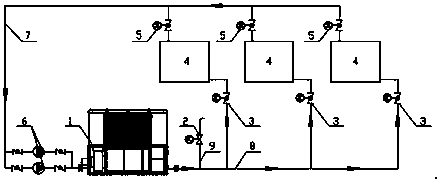
[0017] The following combination figure 1 , the technical content, structural features, achieved goals and effects of the present invention will be described in detail through preferred embodiments.

[0018] Such as figure 1 As shown, the transformer drying system provided by the present invention includes: a heat storage device 1, which has an air inlet and an air outlet, and stores heat during the low-peak power consumption period; The air inlet of the device 1 is connected; multiple transformer drying rooms 4 are placed inside to place the transformers to be dried; each transformer drying room 4 is respectively connected to the air outlet of the heat storage device 1 through the air duct system, and connected to each induced draft fan 6 ; Wherein, the heat storage device 1, the induced draft fan 6 and the transformer drying room 4 form a thermal cycle loop through the air duct system; during the peak power consumption period, the circulating air circulating in the air duct...


PUM


Abstract

The invention relates to a transformer drying system. The transformer drying system comprises a heat storage device, at least one draught fan and a plurality of transformer drying rooms. The heat storage device is provided with an air inlet and an air outlet and conducts heat storage in the low-ebb electricity using period. The draught fans are connected with the air inlet of the heat storage device through an air duct system. To-be-dried transformers are placed into the transformer drying rooms, and the transformer drying rooms are each connected with the air outlet of the heat storage devicethrough the air duct system and connected with the draught fans. The heat storage device, the draught fans and the transformer drying rooms constitute a hot circulation loop through the air duct system. During the peak electricity using period, circulating air circulating in the air duct system is pressurized through the draught fans, then enters the heat storage device, is subjected to heat exchanging, then enters the transformer drying rooms to dry transformer coils, circularly returns to the draught fans and is pressurized again. Low-ebb electricity is fully utilized to heat heat-accumulators, and the transformers are dried through the circulating hot air; and peak load shaving can also be achieved while heat recycling is guaranteed, the electricity using structure is optimized, and energy is saved.

Description

technical field [0001] The invention relates to a drying system for a transformer, in particular to a drying system capable of drying a transformer by utilizing low-valley electricity. Background technique [0002] At present, in the power industry, transformers are the most common primary power equipment. Before the transformer leaves the factory, its coils need to be dried, and the hot air drying method is the most widely used one at present. [0003] In recent years, about 300 million kVA transformers have been delivered to the factory every year in my country. After each batch of transformers is put into the drying room, the air is directly heated by the electric heating wire for drying. A large amount of electric energy is released into the workshop after one-time use in this process, resulting in a serious waste of energy; at the same time, hot air enters the workshop, which also brings greater thermal pollution to the workshop environment. This obviously does not m...

Claims


Application Information

Patent Timeline
Patent Type & Authority Applications(China)
IPC IPC(8): F26B21/02F26B23/04F26B25/00
CPCF26B21/02F26B23/04F26B25/00
Inventor 唐浩王芳于春雷盛化才杨彬戚风亮叶晨涛彭贞杲刘逸青
Owner SHANGHAI ZHIXIN INTELLIGENT ELECTRIC CO LTD
Learn More