Long-distance horizontal directional drilling and grouting reinforcement technology of water-rich sand layer under building group

A water-rich sand layer and horizontal orientation technology, which is applied in earthwork drilling, wellbore/well components, sealing/isolation, etc., can solve the problems of difficult hole layout, narrow construction space, limited reinforcement range, etc., and avoid demolition Resettlement costs, wide range of sources, good results

Active Publication Date: 2020-04-07
BEIJING CHINA COAL MINE ENG CO LTD
View PDF6 Cites 0 Cited by
  • Summary
  • Abstract
  • Description
  • Claims
  • Application Information

AI Technical Summary

Problems solved by technology

Disadvantages: It is necessary to adopt the form of straight holes on the ground. Due to the influence of the location of the surface buildings (structures) and underground pipelines, it often makes it difficult to arrange the holes. At the same time, the construction occupies the ground road, which brings inconvenience to the traffic and the normal life of the surrounding residents.
Disadvantages: There are disadvantages of limited reinforcement range, narrow construction space, cross-operation, which is not conducive to project progress control

Method used


Image

  • Long-distance horizontal directional drilling and grouting reinforcement technology of water-rich sand layer under building group
  • Long-distance horizontal directional drilling and grouting reinforcement technology of water-rich sand layer under building group
  • Long-distance horizontal directional drilling and grouting reinforcement technology of water-rich sand layer under building group

Examples


Embodiment Construction

[0036] In order to illustrate the present invention more clearly, the present invention will be further described below in conjunction with preferred embodiments and accompanying drawings. Similar parts in the figures are denoted by the same reference numerals. Those skilled in the art should understand that the content specifically described below is illustrative rather than restrictive, and should not limit the protection scope of the present invention.

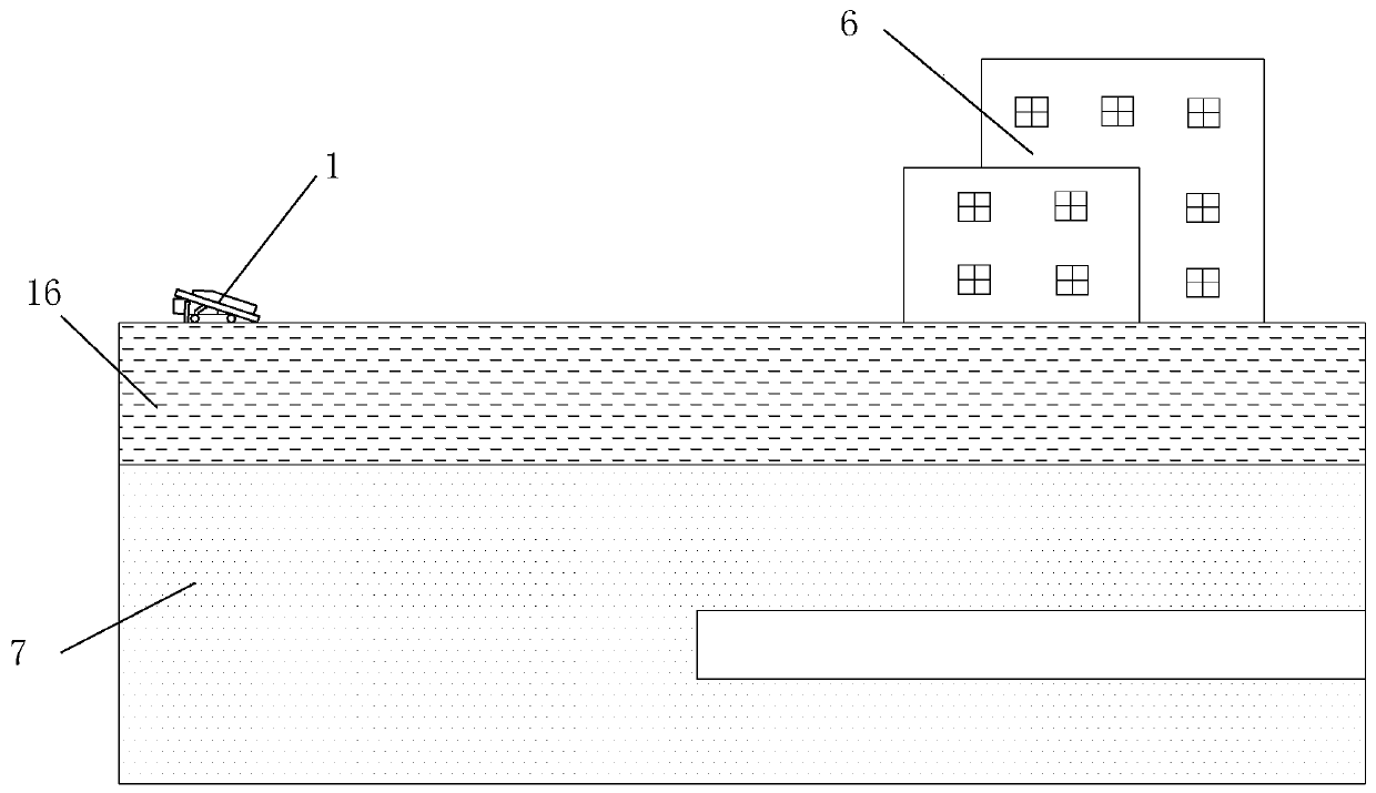
[0037] like Figure 1 to Figure 6 As shown, the long-distance horizontal directional drilling and grouting reinforcement technology of the water-rich sand layer under the building group in this embodiment was tested in the first phase construction project of Guangzhou Rail Transit Line 14 from Dengcun to Jiangpu Station surnamed Zhongwei building group , which specifically includes the following steps:

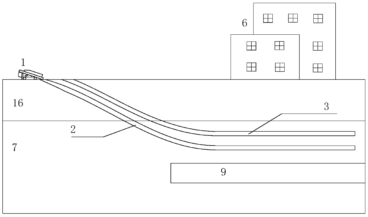
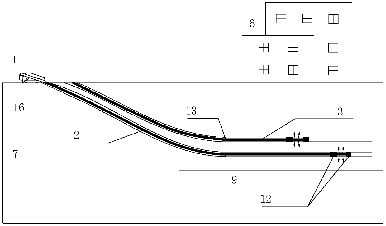
[0038] (a) if figure 2 As shown, the deviated well steerable drilling rig 1 is used on the ground to form a grouting ...


PUM


Abstract

The invention discloses a long distance horizontal directional drilling grouting reinforcing technology of a rich water sand layer under a building complex. The technology comprises the following steps that (a) drilling is conducted on the ground by using an oblique hole guiding drilling rig, grouting drilling comprises a building up section and a horizontal grouting section, wherein the horizontal grouting section is located at the layer position of the to-be-reinforced rich water sand layer, and bare holes are formed in the drilling process of the building up section and the horizontal grouting section; (b) after drilling is completed, a grouting steel valve tube is tripped in, and the grouting steel valve tube is fixed by using a casing material; and (c) during grouting, a hydraulic positioning stop-grouting plug is tripped in to achieve segmented grouting, and a hydraulic type single plug is tripped in to achieve back-type long segment repetitive grouting. According to the long distance horizontal directional drilling grouting reinforcing technology of the rich water sand layer under the building complex, the problem that a traditional straight hole grouting technology is limited by a construction site and a shallow-buried pipeline can be solved, municipal traffic and the normal life of residents are not affected, the effect that reinforcing treatment is conducted on the rich water sand layer under a building at a long distance can be achieved, the compactness and overall bearing capacity of the rich water sand layer are improved, and potential safety hazards such as cracking of the surrounding buildings due to shield construction are prevented.

Description

technical field [0001] The invention relates to the field of grouting reinforcement of water-rich sand layers under municipal buildings (structures), and is especially suitable for shield construction to pass through important buildings (structures) sideways or under important buildings (structures), and around buildings (structures). When the construction conditions are not available, through the construction of directional horizontal drilling, the grouting reinforcement process for the water-rich sand layer under the building can be realized remotely to ensure the safety of the building (structure). Background technique [0002] With the large-scale construction of urban rail transit, most of the subway tunnel constructions pass through the bustling areas of the city, and there are many buildings (structures) on the ground. It is becoming more and more difficult to optimize and arrange the lines. More frequently; and it is very difficult to coordinate the construction of b...

Claims


Application Information

Patent Timeline
IPC IPC(8): E21B33/13E21D9/00C04B28/26C04B28/02
CPCC04B28/02C04B28/26C04B2111/00724C04B2111/70E21B33/13E21D9/001E21D9/002C04B22/124C04B12/04C04B14/10
Inventor 袁东锋李方政袁辉周禹良高晓耕刘书杰董新旺王桦肖炜
Owner BEIJING CHINA COAL MINE ENG CO LTD
Why Eureka
Try Eureka