
Helicopter tail rotor flight control load compensation method

A technology of helicopter tail rotor and compensation method, which is applied in the direction of aircraft transmission, aircraft power transmission, and aircraft power device, etc., can solve the problems of aircraft crash and death, and achieve the effect of reducing the control force

Active Publication Date: 2018-05-22
CHINA HELICOPTER RES & DEV INST
View PDF6 Cites 3 Cited by
  • Summary
  • Abstract
  • Description
  • Claims
  • Application Information

AI Technical Summary

Problems solved by technology

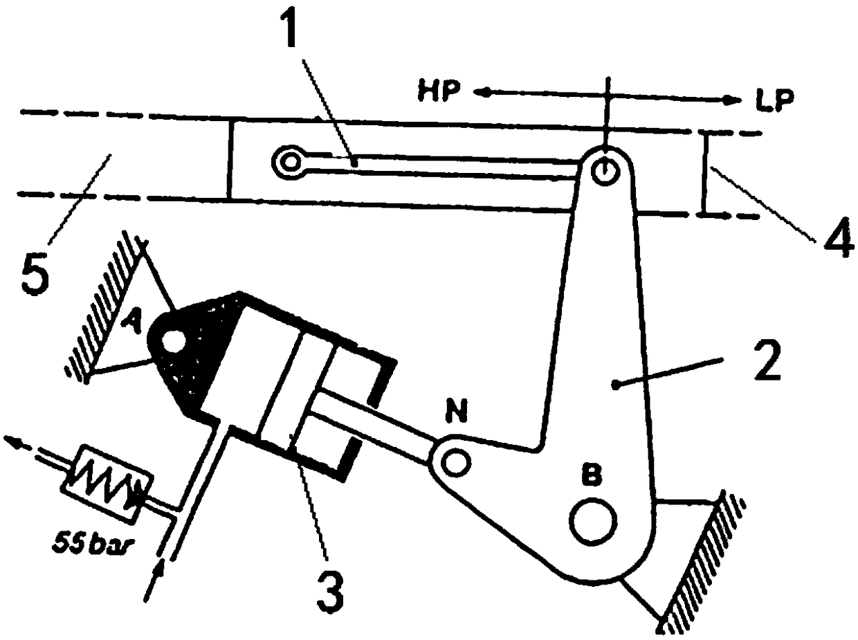
[0004] When the helicopter suddenly encounters hydraulic failure during flight, and the pedals are in a position with a large "external load", it may cause a flight accident due to the failure of the pedals or improper control.

Method used


Image

  • Helicopter tail rotor flight control load compensation method
  • Helicopter tail rotor flight control load compensation method
  • Helicopter tail rotor flight control load compensation method

Examples


Embodiment Construction

[0029] In order to make the objectives, technical solutions and advantages of the present invention clearer, the technical solutions in the embodiments of the present invention will be described in more detail below in conjunction with the drawings in the embodiments of the present invention. In the drawings, the same or similar reference numerals denote the same or similar elements or elements having the same or similar functions throughout. The described embodiments are some, but not all, embodiments of the invention. The embodiments described below by referring to the figures are exemplary and are intended to explain the present invention and should not be construed as limiting the present invention. Based on the embodiments of the present invention, all other embodiments obtained by persons of ordinary skill in the art without creative efforts fall within the protection scope of the present invention. Embodiments of the present invention will be described in detail below ...


PUM


Abstract

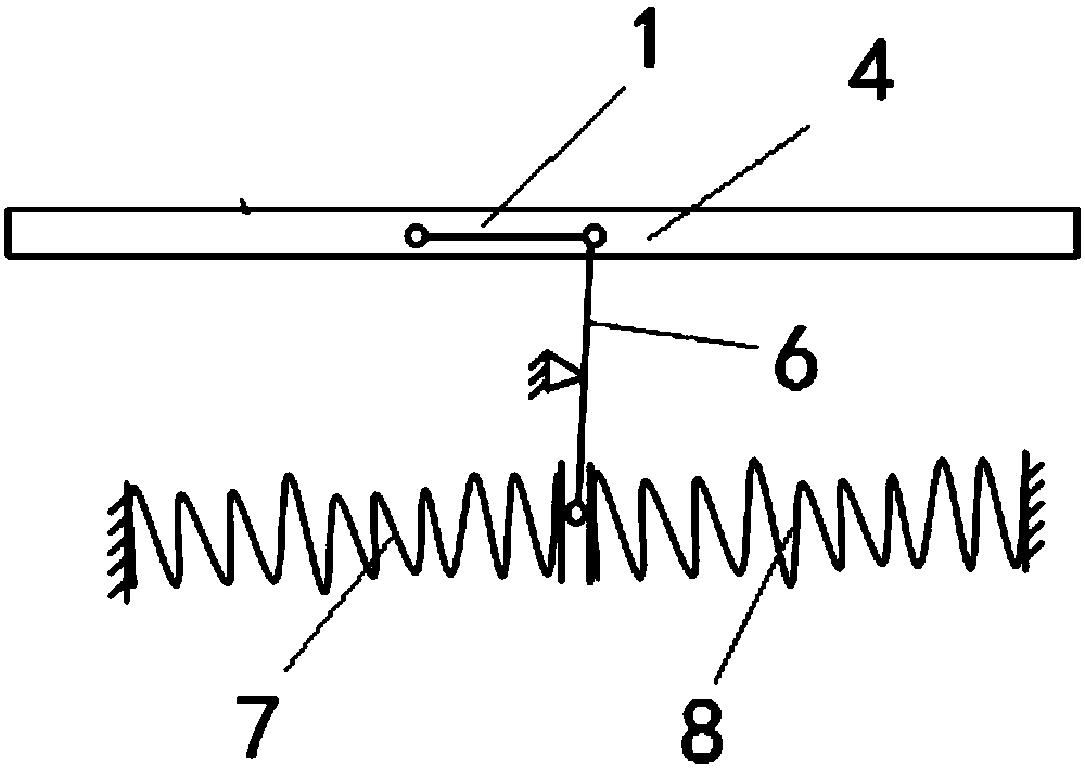
The invention discloses a helicopter tail rotor flight control load compensation method, and belongs to the technical field of helicopter flight control. The helicopter tail rotor flight control loadcompensation method comprises the following steps: Step I, firstly performing theoretical analysis on a tail rotor flight control system mechanism, thus obtaining a relation between an external load F1 and a tail rotor pitch; Step II, designing a load compensation device according to the relation between the external load F1 and the tail rotor pitch, wherein a force output by a load output elementis transmitted to a control line system to reduce a resultant force on the control line system; when a force transmitted from a force F2 output by the load output element to the operation line systemis zero, the corresponding external load F1 at the time is 0; when the external load F1 is 0, a force transmitted from the force F2 output by the load output element to the operation line system through a force transmission line system is matched with the external load F1, and the directions are opposite, so that the resultant force on the control system is reduced. According to the helicopter tail rotor flight control load compensation method, by the adjustment of a reference position, a control force can be further reduced.

Description

technical field [0001] The invention belongs to the technical field of helicopter flight control, and in particular relates to a load compensation method for helicopter tail rotor flight control. Background technique [0002] For light helicopters of 2 tons or less, it is usually necessary to meet the requirements of being able to operate without assistance (usually hydraulic assistance). The pilot controls the helicopter to overcome the friction of the control system and the effect of "external load". The friction force of the control system is an inherent characteristic. In order to reduce the pilot's control force, the most effective measure is to reduce the "external load" of the control system of the system. The "external load" is usually related to the structure of the tail rotor, and the size of the "external load" is also related to the position of the control system. [0003] Taking a certain type of aircraft as an example, the "external load" of the control system...

Claims


Application Information

Patent Timeline
Patent Type & Authority Applications(China)
IPC IPC(8): B64C13/28
CPCB64C13/28
Inventor 张根源邓海侠赵良冯航
Owner CHINA HELICOPTER RES & DEV INST
Learn More