
Conductive disconnecting link of disconnecting switch, gear box of conductive disconnecting link and gear box body

A technology of conductive knife and isolating switch, which is applied in electrical switches, air switch parts, circuits, etc., can solve the problems of not being able to observe the meshing of the gear and the rack, affecting the meshing accuracy of the gear and the rack, etc.

Active Publication Date: 2018-05-18
HENAN PINGGAO ELECTRIC +3
View PDF7 Cites 2 Cited by
  • Summary
  • Abstract
  • Description
  • Claims
  • Application Information

AI Technical Summary

Problems solved by technology

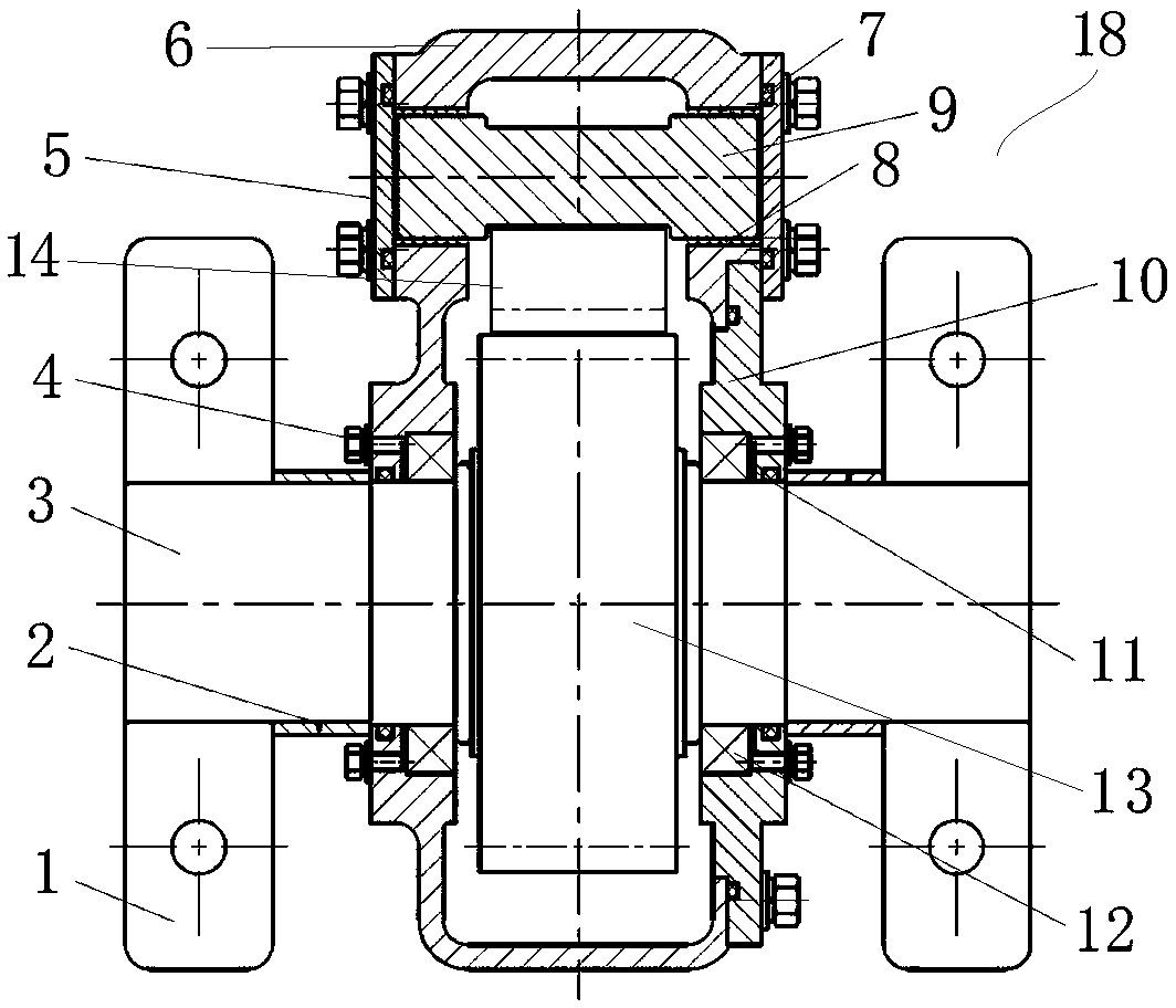
[0007] The purpose of the present invention is to provide a gear box with an end cover to expose the meshing part of the gear, so as to solve the problem that the meshing of the gear and the rack cannot be observed when the two-lobed gear box in the prior art is docked , which affects the meshing accuracy of the gear and the rack; the present invention also provides a gear box using the conductive knife of the gear box body; the present invention also provides a gear box using the conductive knife Conductive blades for disconnectors

Method used


Image

  • Conductive disconnecting link of disconnecting switch, gear box of conductive disconnecting link and gear box body
  • Conductive disconnecting link of disconnecting switch, gear box of conductive disconnecting link and gear box body
  • Conductive disconnecting link of disconnecting switch, gear box of conductive disconnecting link and gear box body

Examples


Embodiment Construction

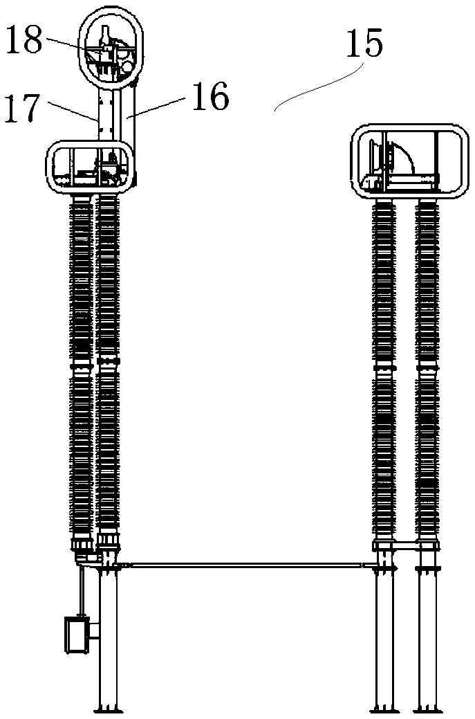
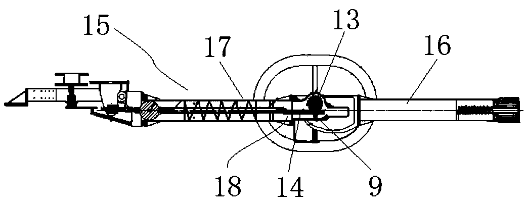
[0044] Embodiment 1 of the conductive switch blade of the isolating switch of the present invention is as Figure 3 to Figure 4 As shown, it includes an upper conductive pipe (not shown in the figure), a lower conductive pipe (not shown in the figure) and a gear box 18 connecting the upper conductive pipe and the lower conductive pipe. The gear box 18 includes a gear box body, and the gear box body includes a box body 6 and an end cover 10 arranged on one side of the box body 6. In other embodiments, the end cover 10 can also be arranged on the side of the box body 6. sides. The position of the box body 6 corresponding to the end cover 10 is provided with an end cover installation hole, and the diameter of the end cover installation hole is larger than the diameter of the gear 13, so that the gear 13 can be loaded into the box body 6 from the end cover installation hole, and can also be exposed. The meshing portion of the gear 13 and the rack 14; the mounting hole of the end ...


PUM


Abstract

The invention relates to a conductive disconnecting link of a disconnecting switch, a gear box of the conductive disconnecting link and a gear box body. The conductive disconnecting link of the disconnecting switch comprises an upper conductive tube, a lower conductive tube and a gear box which is connected with the upper conductive tube and the lower conductive tube; the gear box comprises a gearbox body; a gear shaft for assembling a gear is arranged in the gear box body by means of bearing transmission; a rack matched with the gear is arranged in the gear box body; the gear box body comprises a box body unit; end cover mounting holes which are used for exposing the meshing portions of the gear and located in at least one side of the gear shaft are formed in the box body unit; the end cover mounting holes are provided with end covers; and the corresponding ends of the gear shaft are rotationally arranged on the end coves. According to the gear box body, the box body unit and the endcovers are installed in a matched manner; the end cover mounting holes can expose the meshing portions of the gear; and when the end covers are arranged on the box body unit, the meshing conditions of the gear and the rack can be observed through the end cover mounting holes, and therefore, the meshing accuracy of the gear and the rack can be ensured.

Description

technical field [0001] The invention relates to a conductive switch knife of an isolating switch, a gear box of the conductive knife knife and a box body of the gear box. Background technique [0002] The high-voltage isolating switch is a switching device mainly used for line switching under no-current-carrying conditions, and for electrically isolating high-voltage busbars, circuit breakers and other equipment and high-voltage lines to be overhauled. It can provide a Meet the requirements of the insulating environment. [0003] The application publication number is CN106504933A, and the Chinese patent application with the publication date of 2017.03.15 discloses a large-capacity high-voltage DC isolating switch. The structure of the high-voltage DC isolating switch is as follows: Figure 1 to Figure 2 As shown, the conductive switch knife 15 is included, the conductive switch knife 15 includes an upper conductive tube 16 and a lower conductive tube 17, a gear box 18 is ins...

Claims


Application Information

Patent Timeline
Patent Type & Authority Applications(China)
IPC IPC(8): H01H31/02
CPCH01H31/026
Inventor 孙玉洲王占杰高坚李宇鹏李宏楼李付永王巧红夏立国王路平郭川李竞师丽芳郭海涛邱正新朱承治
Owner HENAN PINGGAO ELECTRIC
Learn More