
A spectral imaging device

A spectral imaging and spectral technology, which is applied in the field of spectral imaging systems, can solve the problems of high optical complexity and increased scattered light, and achieve the effects of good imaging quality, fewer optical components, high spectral resolution and spatial resolution

Active Publication Date: 2020-07-17
NINGBO YUANLU ELECTRO OPTICS
View PDF6 Cites 0 Cited by
  • Summary
  • Abstract
  • Description
  • Claims
  • Application Information

AI Technical Summary

Problems solved by technology

For large numerical aperture (NA ≥ 0.2) system design, in order to collimate the light, multiple spherical lenses or multiple aspheric lenses are used, which makes the optical complexity higher and the scattered light also increases.

Method used


Image

  • A spectral imaging device
  • A spectral imaging device
  • A spectral imaging device

Examples


Embodiment Construction

[0057] The improved small-scale spectral imaging system will be further elaborated in conjunction with the accompanying drawings and embodiments.

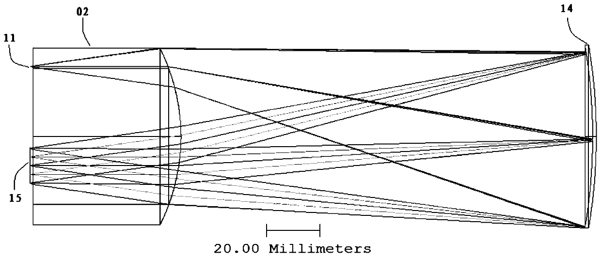
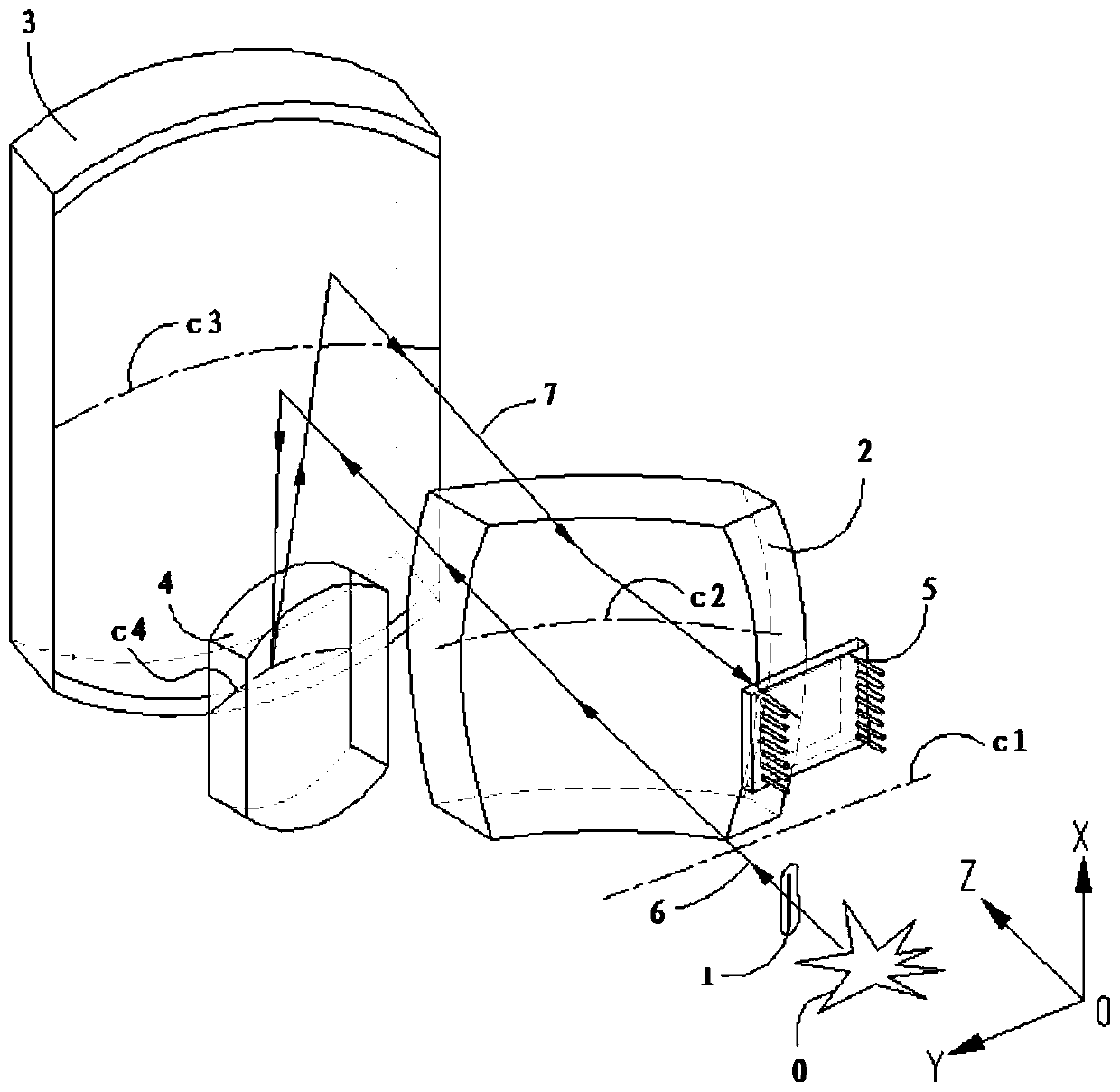
[0058] exist Figure 3 to Figure 20 In the illustrated embodiment, the improved system provides an optical device for the imaging function and improved image quality function of non-spectrally dispersed light passing through the slit or pinhole into the spectrograph Reaching a convex diffraction grating, where the spectrally dispersed light is then focused onto a detector using the same optics. This method greatly reduces spectral line bending and chromatic aberration, and these designs have significant advantages over offner-type and Dyson-type designs.

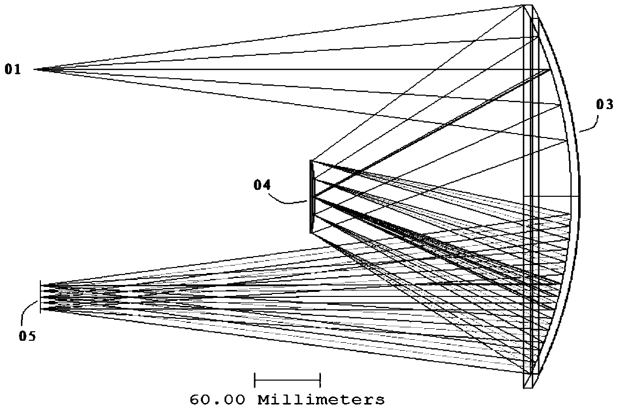
[0059] like image 3 As shown, the conventional offner spectrometer figure 1 Including a large concave mirror 03, its aperture size is 420mm in diameter, which makes the volume and weight of the instrument relatively large. The example of the present invention provides a pers...


PUM

PropertyMeasurementUnit
thicknessaaaaaaaaaa
sphericityaaaaaaaaaa

Abstract

The invention relates to a spectrum imaging device; incident lights are transmitted to an incident slit or a pin hole; the second optical assembly is a refraction correction mirror used for guiding the incident lights onto a recessed surface reflector; the reflected lights irradiate on a convex surface reflection diffraction grate, thus enabling dispersive spectrum to irradiate on the same recessed surface reflector; the spectrum penetrates the same second optical assembly and is focused on a detector; the incident slit and detector are preferably symmetrically distributed up and down with respect to the central line of the refraction correction mirror, thus enabling the incident slit member to be far away from the detection surface, and ensuring a large size detector or a device mounted on the spectrum imaging system not to shield the incident slit member.

Description

technical field [0001] The present invention relates to a spectral imaging system for high-resolution hyperspectral imagers and dispersive spectrographs, in particular to a spectral imaging system with high luminous flux, high grating diffraction efficiency and Designed with optical design for excellent spectral and spatial imaging qualities Background technique [0002] A spectroscopic instrument is a device that separates the light under study into wavelengths or wavelength regions (spectrum) with a certain energy, and measures the intensity of each wavelength with relative intensity. Analysis of the spectrum of electromagnetic radiation reflected from or emitted by an object can help identify the chemical composition or physical properties of the substance under study. Which element can be determined according to the wavelength, which is the qualitative analysis of the spectrum; and the content of the element can be obtained by measuring the intensity of the wavelength, ...

Claims


Application Information

Patent Timeline
Patent Type & Authority Patents(China)
IPC IPC(8): G01J3/12G01J3/28
CPCG01J3/12G01J3/2823
Inventor 祝晓勇相连钦
Owner NINGBO YUANLU ELECTRO OPTICS
Learn More