
Gear teeth thickness measurement method based on line structured light

A technology of line structured light and gear teeth, which is applied in the direction of measuring devices, optical devices, instruments, etc., can solve the problems of slow measurement speed, probe wear radius compensation, difficult gear tooth thickness measurement, etc., to improve measurement efficiency, The effect of reducing random errors and fast measurement speed

Active Publication Date: 2018-05-18
BEIJING UNIV OF TECH
View PDF5 Cites 18 Cited by
  • Summary
  • Abstract
  • Description
  • Claims
  • Application Information

AI Technical Summary

Problems solved by technology

[0004] Commonly used contact measurement methods have the following disadvantages: 1. Slow measurement speed and low efficiency
It is difficult to measure the tooth thickness of all gear teeth in a short time by the contact method, and the measurement efficiency is not high when testing a large number of gears
2. It is difficult to accurately locate on the graduated cylindrical surface for detection
The commonly used tooth thickness measurement method is difficult to accurately locate and measure on the graduated cylindrical surface. Generally, the arc tooth thickness or chord tooth thickness on other evaluation cylindrical surfaces is used for characterization
3. There are problems such as wear and radius compensation of the probe
The contact measurement method will inevitably cause measurement errors due to wear of the probe, and radius compensation must be performed according to the type of probe during measurement

Method used


Image

  • Gear teeth thickness measurement method based on line structured light
  • Gear teeth thickness measurement method based on line structured light
  • Gear teeth thickness measurement method based on line structured light

Examples


Embodiment Construction

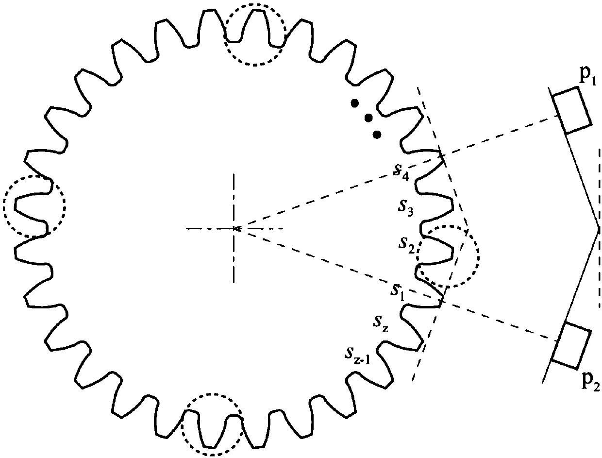
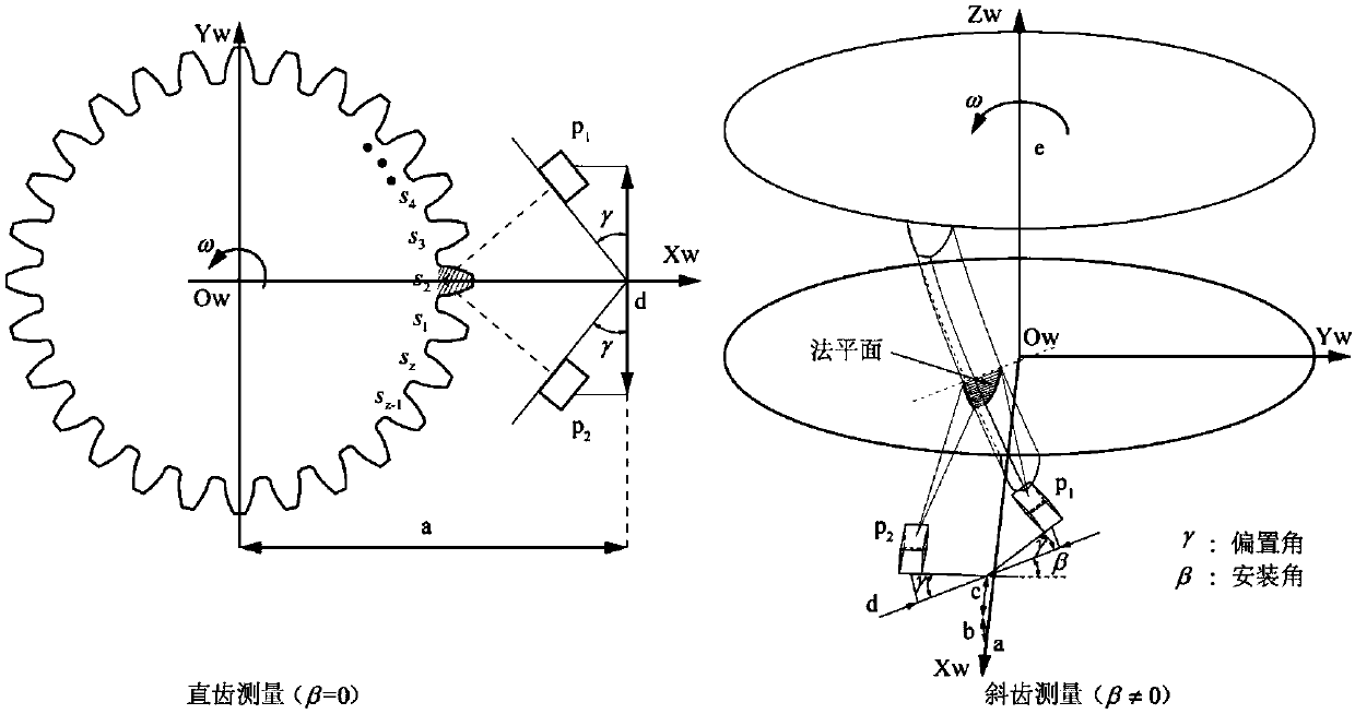
[0061] A gear tooth thickness measurement method based on line structured light will be further described below with reference to the accompanying drawings. like Figure 6 , this method can be applied to both the vertical measuring machine and the horizontal measuring machine, and the vertical measuring machine is taken as an example for illustration.

[0062] The vertical measuring machine includes a spindle unit, a measuring unit and a machine bed, and the spindle unit and the measuring unit are installed on the bed. The spindle unit includes the spindle and fixed chuck, θ 1 The axial circular grating is connected to the main shaft; the surveying unit includes a Z-direction moving rod, an X-direction moving rod, an angle adjustment arm and a structured light probe. The Z-axis grating is installed on the measuring X-direction moving rod to measure the movement of the Z-axis. Measure the movement of the surveying unit along the X direction on the Z axis, the angle adjustment...


PUM


Abstract

The invention discloses a gear teeth thickness measurement method based on line structured light and belongs to the field of the precision test technology and instruments and the gear detection technology. After a detected gear is embedded, the center of a coordinate system is calibrated through a line laser probe, the design reference of the detected gear is selected as the reference for measurement, according to gear parameters, more than 4 gears uniformly distributed on the detected gear are selected, and three uniformly-distributed cross sections of each gear are taken as measurement positions; data acquisition, mounting parameters required by two probes and the relationship among the parameters are calculated according to the parameters of the detected gear, two line structured lightprobe coordinate systems are established, and data of two side surfaces of the detected gear is acquired; according to each mounting parameter and the measurement data, a space coordinate conversion formula for data acquisition is established, and each set of measurement values of the probe coordinate systems is converted to the gear design center. The method is advantaged in that a tooth thickness deviation mathematic model is established, and high precision measurement of tooth thickness deviation, string tooth thickness measurement and separate-tooth thickness average deviation is further realized.

Description

technical field [0001] The invention relates to a gear tooth thickness measurement method based on line structured light, which belongs to the technical fields of precision testing technology, instrument and gear detection. Background technique [0002] Tooth thickness measurement is the most important dimensional value used to evaluate the entire gear, and it is one of the most critical indicators when gears are matched with each other. Gear matching and installation must ensure the minimum backlash of the gear pair and limit the maximum backlash. The backlash of the gear pair is realized by reducing the tooth thickness and adjusting the center properly in the gear processing. When the matching gear is in transmission, if the backlash is too small, the lubricating oil film between the two tooth surfaces will be destroyed, and if the backlash is too large, it will affect the transmission stability, generate noise and return error, etc. Secondly, when the gear pair is runni...

Claims


Application Information

Patent Timeline
Patent Type & Authority Applications(China)
IPC IPC(8): G01B11/06
CPCG01B11/06
Inventor 石照耀王涛
Owner BEIJING UNIV OF TECH
Learn More