
Electromagnetic drying chamber

A drying room, electromagnetic technology, applied in drying, dryer, drying gas layout and other directions, can solve the problems of low drying efficiency, lack of natural resources, waste of resources, etc., to achieve rapid heating process and high heat utilization rate , the effect of saving energy

Pending Publication Date: 2018-05-18
宁夏鑫润源节能科技有限公司 +1
View PDF5 Cites 3 Cited by
  • Summary
  • Abstract
  • Description
  • Claims
  • Application Information

AI Technical Summary

Problems solved by technology

[0002] Existing drying rooms often use coal or gas as a heating medium, and release heat through heat sinks, heat the air, and then dry objects; due to the lack of natural resources and the need for environmental protection, at the same time, coal or gas heating also There is a defect of low thermal efficiency, so this heating method has been gradually replaced by a heating method using energy-saving and efficient clean energy
In addition, hot and humid steam will be generated during the drying process of the object. These hot and humid steam must be processed through a specific waste heat recovery system in time, and finally the excess moisture will be discharged through the exhaust port of the dehumidification air duct, otherwise it will cause drying. Dry efficiency is low, resulting in unnecessary waste of resources

Method used


Image

  • Electromagnetic drying chamber
  • Electromagnetic drying chamber
  • Electromagnetic drying chamber

Examples


Embodiment Construction

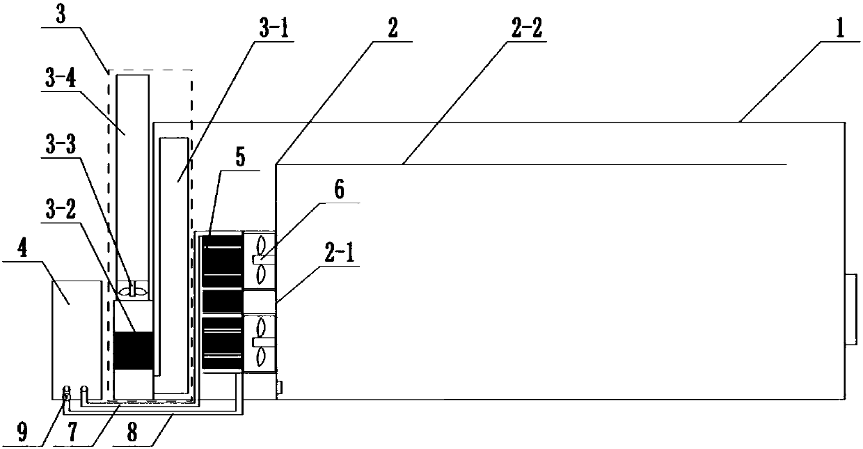
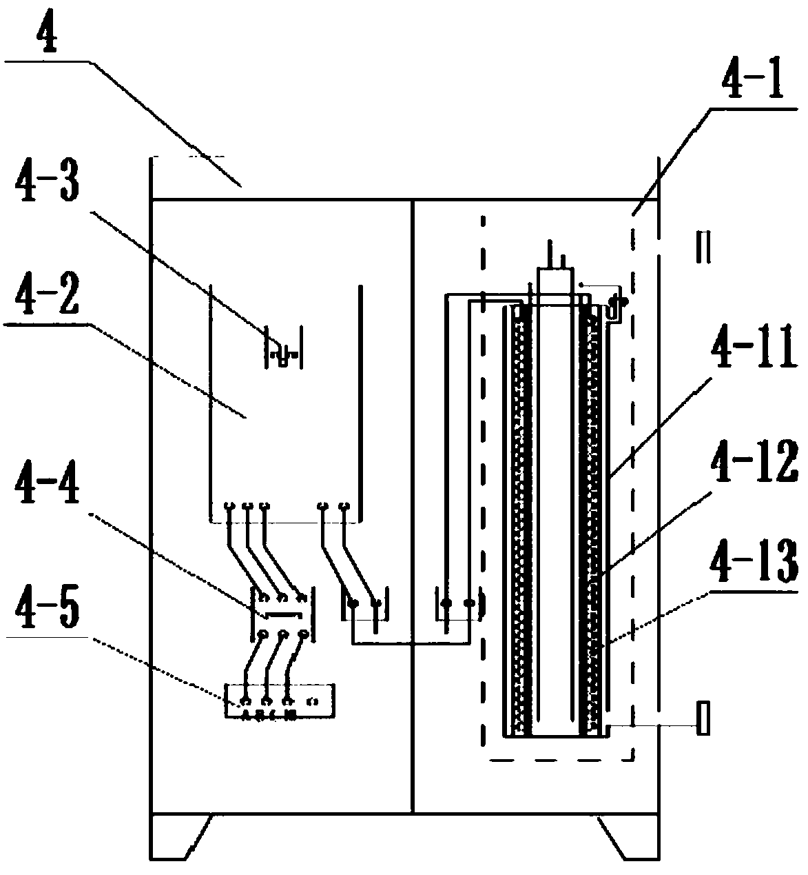
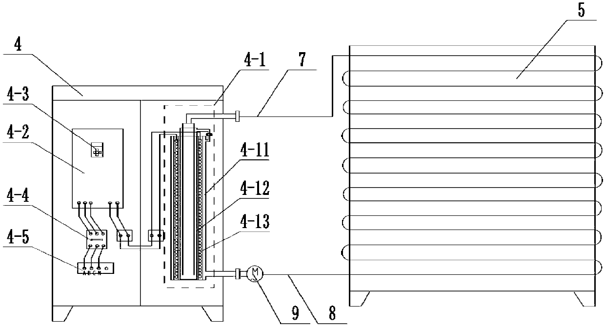
[0016] Such as Figure 1 to Figure 3 As shown, an electromagnetic drying chamber includes a chamber body 1, a partition 2, a moisture removal device 3, a heating device 4, a surface cooler 5, a high-temperature fan 6, a heat conduction pipe 7, a heat conduction pipe 8 and a circulation Pump 9; the chamber body 1 is a square cavity structure, the partition 2 is located inside the chamber body 1, the partition 2 includes a first partition 2-1 and a second partition 2-2 connected to each other, the first partition 2- 1 is vertically arranged, and one end of it is connected to the bottom of chamber body 1, and the other end leaves a gap with the top of chamber body 1; There are gaps on the side wall and the right side wall, the material of the chamber body 1 is polyurethane board, and the material of the partition board 2 is heat insulation board; the dehumidification device 3 includes the internal moisture pipe 3-1 and the heat exchanger 3-2 connected in sequence , dehumidificat...


PUM


Abstract

The invention belongs to the technical field of drying equipment and relates to an electromagnetic drying chamber. The drying chamber comprises a chamber body, partition plates, a moisture dischargingdevice, a heating device, a surface air cooler, a high-temperature fan, a heat conduction liquid outlet pipe, a heat conduction liquid inlet pipe and a circulation pump. The partition plates comprisethe first partition plate and the second partition plate; the moisture discharging device comprises an inner moisture pipe, a heat exchanger, a moisture discharging fan and an outer moisture discharging pipe which are sequentially connected; the heating device comprises an electromagnetic inductor, an electromagnetic heating controller, a display, a three-phase short-circuit protection switch anda three-phase four-wire connecting terminal; and the electromagnetic inductor comprises a metal heating body, a heat insulation layer and an induction coil. By utilizing the electromagnetic drying chamber, through the electromagnetic heating principle, the metal heating body emits heat and heats a heat conduction medium, the heat energy loss is less, energy is saved, and the heat utilization rateis high; through air duct circulation and the design of the moisture discharging device, temperature control is accurate, and the drying efficiency is high; and through complete separation of heat conduction liquid and a circuit, safety and environmental protection are achieved, and the life is long.

Description

technical field [0001] The invention belongs to the technical field of drying equipment and relates to an electromagnetic drying chamber, in particular to a drying chamber which is heated and dried by electromagnetic induction. Background technique [0002] Existing drying rooms often use coal or gas as a heating medium, and release heat through heat sinks, heat the air, and then dry objects; due to the lack of natural resources and the need for environmental protection, at the same time, coal or gas heating also There is a defect of low thermal efficiency, so this heating method has been gradually replaced by a heating method using energy-saving and efficient clean energy. In addition, hot and humid steam will be generated during the drying process of the object. These hot and humid steam must be processed through a specific waste heat recovery system in time, and finally the excess moisture will be discharged through the exhaust port of the dehumidification air duct, other...

Claims


Application Information

Patent Timeline
Patent Type & Authority Applications(China)
IPC IPC(8): F26B9/02F26B21/00F24H7/04F24H9/18H05B6/02H05B6/06H05B6/36
CPCH05B6/02H05B6/06H05B6/36F24H7/0416F24H9/1863F26B9/02F26B21/002F24H2250/08
Inventor 吴西锋高金保
Owner 宁夏鑫润源节能科技有限公司
Learn More