
Crude oil safety heating tank special for crude oil transportation

A technology for heating tanks and crude oil, which is applied in the direction of transporting passenger cars, transportation and packaging, tank cars, etc., can solve problems such as safety accidents, achieve uniform heating and avoid excessive pressure

Inactive Publication Date: 2018-05-18
成都君华睿道科技有限公司
View PDF1 Cites 1 Cited by
  • Summary
  • Abstract
  • Description
  • Claims
  • Application Information

AI Technical Summary

Problems solved by technology

[0008] The invention provides a crude oil safety heating tank specially used for crude oil transportation to solve the technical problem that safety accidents easily occur due to the aging of electric heating lines in the prior art

Method used


Image

  • Crude oil safety heating tank special for crude oil transportation
  • Crude oil safety heating tank special for crude oil transportation
  • Crude oil safety heating tank special for crude oil transportation

Examples


Embodiment 1

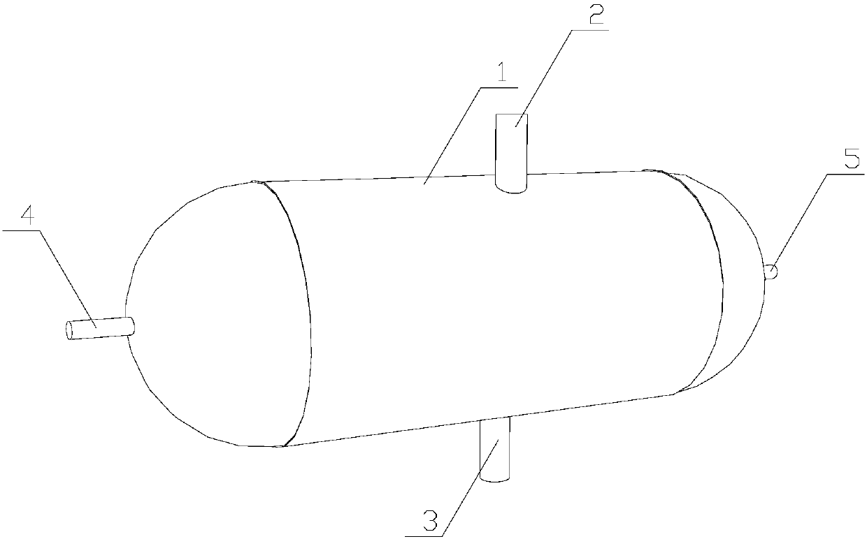
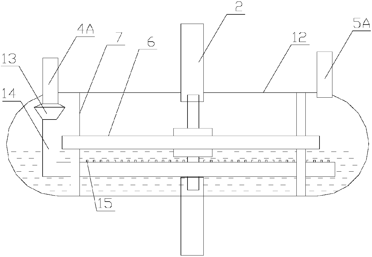
[0030] figure 1 combine figure 2 As shown, the liquid level control device in the tank includes a floating plate 6 floating on the oil surface and at least three guide columns 7 fixed inside the oil tank body 1, and guide columns corresponding to the guide columns 7 are provided on the floating plate 6. hole, the guide post 7 is sleeved in the guide hole, and the upper and lower sides of the floating plate 6 are provided with plugging structures corresponding to the oil inlet pipe 2 and the oil outlet pipe 3 respectively. The columnar oil quantity plug 9 on the elastic plugging column 8 is formed.

[0031] When the floating plate 6 moves upward with the oil level, when the liquid level reaches a certain position, the elastic plugging column 8 on the upper side of the floating plate 6 enters the oil inlet pipe 2 to reduce the amount of oil entering, until the liquid level reaches the highest position, the elastic The plugging column 8 seals the bottom of the oil inlet pipe 2...

Embodiment 2

[0038] like image 3 As shown, the liquid level control device in the tank is the same as that in Example 1, and the oil is heated by inert gas with temperature.

[0039] The oil tank body 1 is provided with an air inlet pipe 4A and an air outlet pipe 5A extending to the inside of the oil tank body 1, and the ends of the air inlet pipe 4A and the air outlet pipe 5A located in the oil tank body 1 are higher than the oil liquid level, The air intake pipe 4A is located at the bottom of the end in the oil tank body 1 and is connected with an air diffuser 14. The end of the air diffuser 14 is sealed away from the end of the air intake pipe 4A, and the part of the air diffuser 14 located in the oil liquid is evenly distributed with diffusers. Air tubules15.

[0040] In this embodiment, in order to utilize the device smoothly, before the oil enters, the inert gas with high pressure and temperature is passed through the air intake pipe 4A, and the air flow erupted at the air diffuser...

Embodiment 3

[0046] like Figure 4 As shown, the oil heating method is the same as that of Example 1, but the liquid level control device in the tank is different. The columnar oil volume plug 9 is set as a conical oil volume plug 9A, so that the flow of oil into or out of the tank gradually increases. Variety.


PUM


Abstract

The invention provides a crude oil safety heating tank special for crude oil transportation, and relates to the technical field of oil and gas exploitation safety control. The crude oil safety heatingtank comprises an oil tank body, an oil inlet pipe, an oil outlet pipe, an oil heating structure and an internal liquid level control device, wherein the oil tank body is composed of an inner shell and an outer shell which are arranged in a sleeving manner inside and outside; the inner shell is used for storing oil; a cavity between the inner shell and the outer shell is an insulating cavity; a hot water injection pipe and a recycling pipe which extend into the insulating cavity, and a gas inlet pipe and a gas outlet pipe which extend into the inner shell are arranged on the outer shell; theend parts, positioned in the inner shell, of the gas inlet pipe and the gas outlet pipe are higher than the oil level; the end part, positioned in the inner shell, of the gas inlet pipe is connected with a gas dispersion pipe; the end part of the end, away from the gas inlet pipe, of the gas dispersion pipe is sealed; and gas dispersion small pipes are uniformly distributed at the part, positionedin oil, of the gas dispersion pipe.

Description

technical field [0001] The invention relates to the technical field of oil and gas exploitation safety control, in particular to a crude oil safety heating tank specially used for crude oil transportation. Background technique [0002] When the existing crude oil storage tank is in operation, it is necessary to observe the liquid level on site and manually control the electric heating and oil well motor control device. If the operation is not timely, it is easy to cause safety accidents. The crude oil in the tank freezes, the pipeline freezes and cracks, and oil leaks and other accidents. When the liquid level in the crude oil storage tank reaches the upper limit of the safe liquid level, if it is not found in time, it is easy to cause a tank accident of the crude oil storage tank; when the liquid level in the crude oil storage tank reaches the lower limit of the safe liquid level, it is easy Cause the heating device to burn dry and cause a fire accident. [0003] The inve...

Claims


Application Information

Patent Timeline
Patent Type & Authority Applications(China)
IPC IPC(8): B65D88/74B65D88/06B65D90/00B65D90/24
CPCB65D88/744B65D88/06B65D90/00B65D90/24
Inventor 曹月琴
Owner 成都君华睿道科技有限公司
Learn More