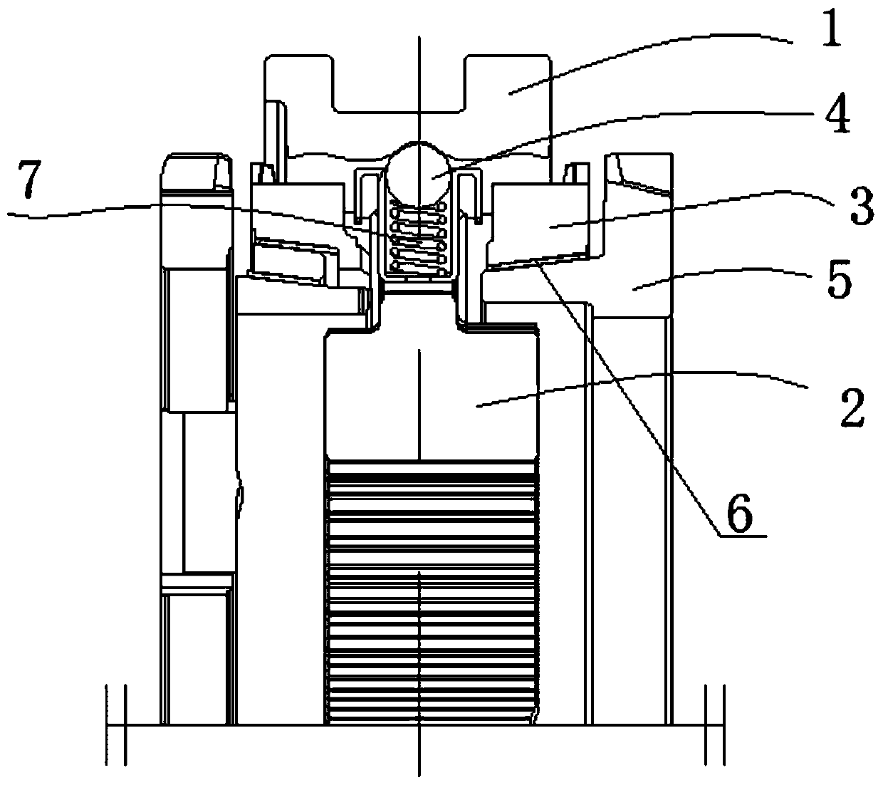
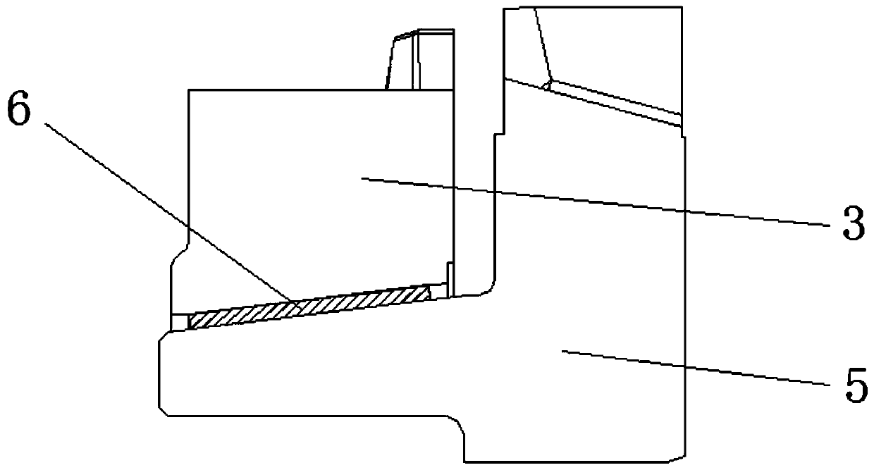
A car synchronizer device
A synchronizer and automobile technology, which is applied in the direction of clutches, mechanical drive clutches, mechanical equipment, etc., can solve the problems of limited transmission shift speed and small friction area, and achieve the goals of shortening shift stroke, increasing friction area, and reducing weight Effect
- Summary
- Abstract
- Description
- Claims
- Application Information
AI Technical Summary
Problems solved by technology
Method used
Image
Examples
Embodiment 1
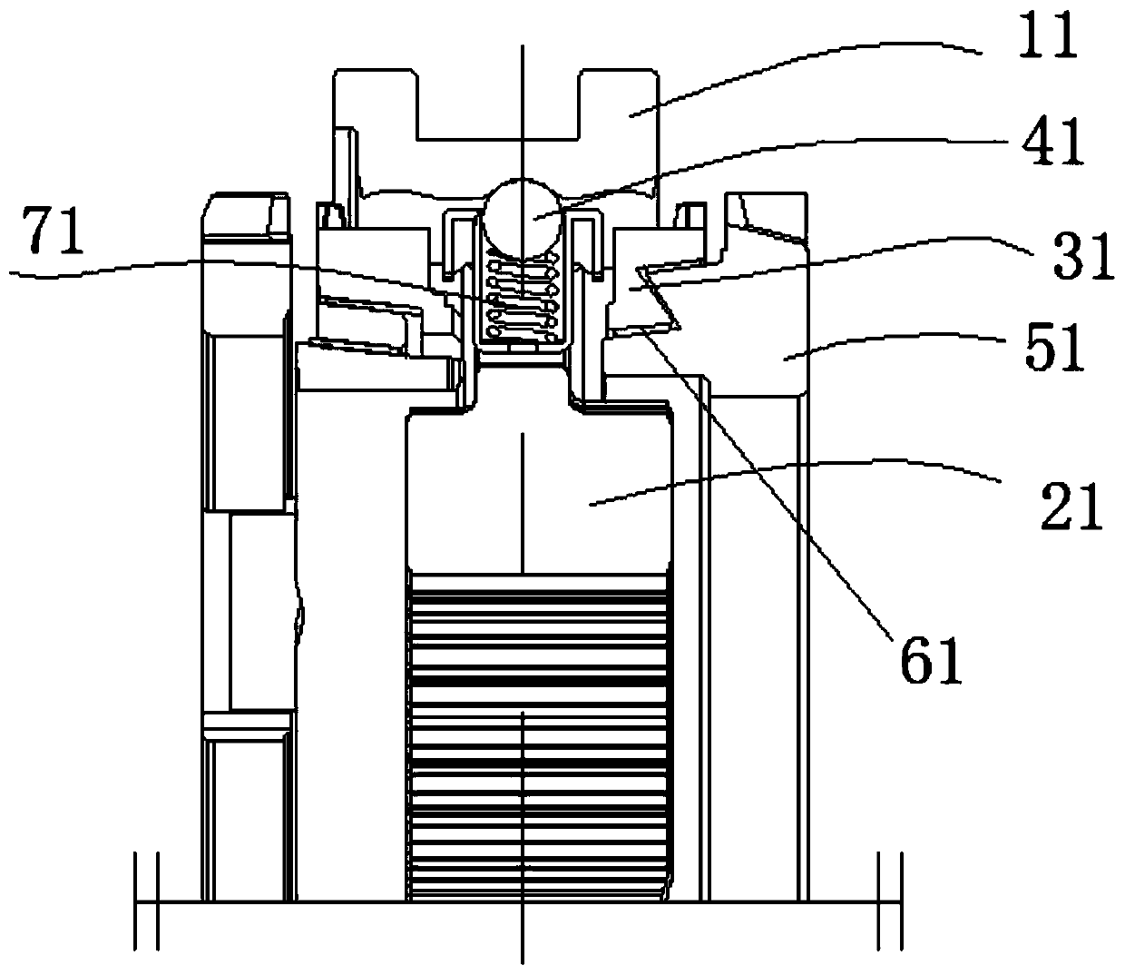
[0029] see Figure 3-4 . As shown in the figure, the present invention discloses an automobile synchronizer device, including a gear sleeve 11, a gear hub 21, a synchronizing ring 31 and engaging teeth 51. The gear sleeve 11 is sleeved on the gear hub 21, and the The engaging tooth 51 is arranged at one end of the gear hub 21, and a groove is arranged in the engaging tooth 51, and the synchronizing ring 31 is arranged in the groove, and there is a gap between the synchronizing ring 31 and the engaging tooth 51. Z-shaped contact surface, the contact surface includes a first contact surface 8, the first contact surface 8 forms a preset angle with the central axis of the gear hub 21, there are two first contact surfaces 8, the A friction layer 61 is provided on the first contact surface 8, the sum of the lengths of the friction layer 61 is greater than the radius of the synchronous ring 31, the friction layer 61 is pasted on the synchronous ring 31, and the friction layer 61 has...
Embodiment 2
[0032] The invention discloses an automobile synchronizer device, which comprises a gear sleeve 11, a gear hub 21, a synchronizing ring 31 and engaging teeth 51. The gear sleeve 11 is sleeved on the gear hub 21, and the engaging teeth 51 are arranged on the At one end of the gear hub 21, a groove is arranged in the engaging tooth 51, and there is a zigzag contact surface between the synchronous ring 31 and the engaging tooth 51, and the contact surface includes a first contact surface 8. The first contact surface 8 and the central axis of the gear hub 21 are arranged perpendicular to each other. There are three first contact surfaces 8, and the three first contact surfaces 8 are arranged parallel to each other. There is a friction layer 61 , the sum of the lengths of the friction layer 61 is greater than the radius of the synchronous ring 31 , and the friction layer 61 is pasted on the synchronous ring 31 . There are three friction layers 61 , a slider 41 is arranged between t...
Embodiment 3
[0034]The invention discloses an automobile synchronizer device, which comprises a gear sleeve 11, a gear hub 21, a synchronizing ring 31 and engaging teeth 51. The gear sleeve 11 is sleeved on the gear hub 21, and the engaging teeth 51 are arranged on the At one end of the gear hub 21, a groove is arranged in the engaging tooth 51, and there is a zigzag contact surface between the synchronous ring 31 and the engaging tooth 51, and the contact surface includes a first contact surface 8. The first contact surface 8 and the central axis of the gear hub 21 are arranged perpendicular to each other. There are four first contact surfaces 8, and the four first contact surfaces 8 are arranged parallel to each other. On the first contact surface 8 A friction layer 61 is provided, and the friction layer 61 is pasted on the synchronization ring 31 . The sum of the lengths of the friction layers 61 is greater than the radius of the synchronous ring 31, there are four friction layers 61, a...
PUM
 Abstract
Description
Claims
Application Information
 - R&D
- Intellectual Property
- Life Sciences
- Materials
- Tech Scout
- Unparalleled Data Quality
- Higher Quality Content
- 60% Fewer Hallucinations
Browse by: Latest US Patents, China's latest patents, Technical Efficacy Thesaurus, Application Domain, Technology Topic, Popular Technical Reports.
© 2025 PatSnap. All rights reserved.Legal|Privacy policy|Modern Slavery Act Transparency Statement|Sitemap|About US| Contact US: help@patsnap.com


