
Impulse type secondary jet flow thrust vector control system

A technology of thrust vector control and secondary jet, applied in jet propulsion devices, rocket engine devices, machines/engines, etc., can solve the problem of increasing secondary flow channels and Coanda effect surfaces, increasing system complexity, structural quality and size and other problems, to achieve the effects of enhanced deflection ability, reduced secondary flow, and low energy consumption

Inactive Publication Date: 2018-05-15
JIANGXI HONGDU AVIATION IND GRP
View PDF7 Cites 8 Cited by
  • Summary
  • Abstract
  • Description
  • Claims
  • Application Information

AI Technical Summary

Problems solved by technology

Although the use of proportional control valves improves the precision of thrust vector control, it increases the secondary flow channel and Coanda effect surface, which increases the complexity of the system and the quality and size of the structure

Method used


Image

  • Impulse type secondary jet flow thrust vector control system
  • Impulse type secondary jet flow thrust vector control system
  • Impulse type secondary jet flow thrust vector control system

Examples


Embodiment Construction

[0023] The present invention will be further described in detail below in conjunction with examples, but the embodiments of the present invention are not limited thereto.

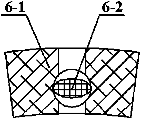
[0024] Such as figure 1 As shown, a pulse type secondary jet thrust vector control system of the present invention includes a rocket engine 1, an annular high-pressure gas storage tank 2, a gas pipeline 3, a pressure stabilizing valve 4, a gas collection chamber 5, a pulse jet control valve 6, Jet nozzle 7 and engine nozzle 8.

[0025] For the rocket engine using the Laval nozzle, the annular high-pressure gas storage tank 2 is set in the peripheral space corresponding to the throat of the engine nozzle 8, and is used as the working medium source of the secondary jet. Transport the secondary jet working medium; filter and adjust the pressure of the secondary jet working medium through the pressure stabilizing valve 4 equipped on the gas pipeline 3; the gas collection chamber 5 is welded on the diffusion se...


PUM


Abstract

The invention relates to an impulse type secondary jet flow thrust vector control system which comprises a rocket engine (1), an annular high pressure gas storage tank (2), a gas transporting pipeline(3), a pressure maintaining valve (4), a gas collecting cavity (5), an impulse jet flow control valve (6), a jet flow spout (7) and an engine jet pipe (8). The system facilitates flight control of anaircraft and adopts the secondary jet flow thrust vector control to reduce energy consumption, enhance the deflection capacity of secondary flow and effectively reduce the flow rate of the secondaryflow needed to be sprayed into.

Description

technical field [0001] The invention relates to a rocket engine secondary jet thrust vector control system, which belongs to the field of rocket engine thrust vector control. Background technique [0002] As a non-traditional flight control technology, thrust vector control technology is widely used in missiles, rockets and other fields. Generally, the attitude of the missile is adjusted by the aerodynamic control force generated by the aerodynamic control surface on the missile body. However, with the improvement of combat requirements and the improvement of the mobility of the attack target, the traditional aerodynamic control method has exposed many difficult problems, such as: low speed in the initial stage of launch, insufficient aerodynamic control force; low air density at high altitudes, reducing control efficiency ; In the final stage of hitting the target, the target may be missed due to insufficient overload and so on. It can be seen that only using traditional ...

Claims


Application Information

Patent Timeline
Patent Type & Authority Applications(China)
IPC IPC(8): F02K9/82
CPCF02K9/82
Inventor 马少杰赵胜海邓波江海涛余文锋袁晓昱张林孙子杰龙海燕
Owner JIANGXI HONGDU AVIATION IND GRP
Learn More