A flapping wing device

A flapper and wing technology, applied in the field of flapper wing devices, can solve the problems of not proposing resistance, not mentioning the concept of providing lift for birds, not designing a flapper, etc., and achieves low production cost and flying effect. Good, simple structure

Active Publication Date: 2017-06-23
吴锜
View PDF16 Cites 0 Cited by
  • Summary
  • Abstract
  • Description
  • Claims
  • Application Information

AI Technical Summary

Problems solved by technology

[0006] At present, according to U.S. Patent No., it is respectively mentioned in the documents of US7255305B2, US7607610 B1, US7215305 B2, US6802473, US7600712, US4139171, US5899408, US7007889, US7963478, US6824094, US7410121 and US7255305 that the asymmetry and The opening and closing of feathers when flapping down, but there is no mention of the concept that this opening and closing provides lift for birds. In many documents and reports, there is no mention of the difference in resistance formed by the wings of birds when they flap up and down. There is no plan to design an orthopter based on the concept of drag difference.

Method used


Image

  • A flapping wing device

Examples


Embodiment

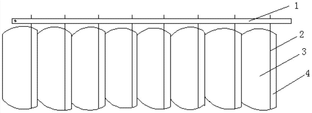
[0018] The main structure of the flapping-wing aircraft wing device involved in this embodiment includes a main frame 1, a feather bar 2, a large vane 3, and a small vane 4; the main frame 1 of a strip structure and 6-20 feather bars of a thin-rod structure, respectively 2Mechanical linkage connection, the feather shaft 2 is hingedly mounted on both sides of the feather shaft 3 and small feather blade 4, the feather shaft 3 and the small feather blade 4 are asymmetrically fixed on the feather shaft 2; the feather shaft 2 follows the flutter The wing device of the wing machine flaps up and down and rotates, and at the same time it drives the large pinnacle 3 and the small pinnacle 4 to unite one by one. The opening and closing of the large pinnacle 3 and the small pinnacle 4 make the flapping wing device have different effective resistance areas when flapping up and down. , The resistance of flapping up and down is different, forming a resistance difference, which provides upward...


PUM


Abstract

The invention belongs to the technical field of ornithopter preparation and particularly relates to an ornithopter wing device. The main body structure comprises a main framework, feather rods, big feather slices and small feather slices. The main framework is in mechanical coordinated connection with 6-20 feather rods. One big feather slice and one small feather slice are installed on the two sides of each feather rod in a hinged mode, and the big feather slice and the small feather slice are of a thin slice structure. The big feather slices and the small feather slices are asymmetrically fixed to the corresponding feather rods. The feather rods rotate along with the up-down fluttering of the ornithopter wing device, and simultaneously drive the big feather slices and the small feather slices to open and close. The effective resistance area of the upward fluttering and the effective resistance area of the downward fluttering of the ornithopter wing device are different due to the opening and closure of the big feather slices and the small feather slices, and the resistance of the upward fluttering and the downward fluttering is different, so that a resistance difference is formed, and climbing power is provided for flying. The design of double-four-connecting-rod of a symmetrical structure is adopted to form a bird wing mechanism, and birdlike flying of an ornithopter is achieved. The ornithopter wing device is simple in structure, scientific in principle and low in manufacturing cost; the flying is simple and convenient to adjust and control; the ornithopter wing device is good in flying effect and broad in application prospect.

Description

[0001] Technical field: [0002] The invention belongs to the technical field of flapping-wing aircraft preparation, and specifically relates to a flapping-wing aircraft wing device, which adopts a symmetrical structure of double four-link design to form a bird wing mechanism and realizes the bird-like flight of the flapping-wing aircraft. [0003] Background technique: [0004] For a long time, people have dreamed of flying in the sky like birds. Many people have imitated the wings of birds and tried to fly without success. People have conducted long-term analysis and research on the principles of bird flight. Some flying principles are found, and the contours of bird wings are found. The upper surface of the wings is arc-shaped. The airflow flowing from above is faster than the airflow flowing from below during flight, thus forming an upward force; for birds flapping After a long period of discussion and research on the principle of wing flight, people have found that in addition t...

Claims


Application Information

Patent Timeline
Patent Type & Authority Patents(China)
IPC IPC(8): B64C33/02
Inventor 吴锜吴开震吴若谷吴若鼎吴若尧
Owner 吴锜
Why Eureka
Try Eureka