


Quick Research
Generate reliable direction feasibility study reports for your R&D in just a few steps.

Technical Q&A
Discover and master advanced knowledge NOW. Basics, ideas, possibilities, all at once.

Find Solutions
As an expert in R&D theories, this can generate solutions to your technical problems instantly.

Evaluate Feasibility
Analyze your overall solution with one click, know your potential R&D risks in advance.

Monitor Landscape
Get weekly tech updates, stay abreast of the latest tech innovations and key insights.
Supporting rack with manually-adjusted height
A technology of manual adjustment and support frame, which is applied in the field of three-dimensional parking garages, can solve the problems of inability to adjust the lifting disc and damage to facilities, and achieve the effect of convenient inspection and maintenance and reduced maintenance costs
- Summary
- Abstract
- Description
- Claims
- Application Information
AI Technical Summary
Problems solved by technology
Method used
Image

Examples
Embodiment 1
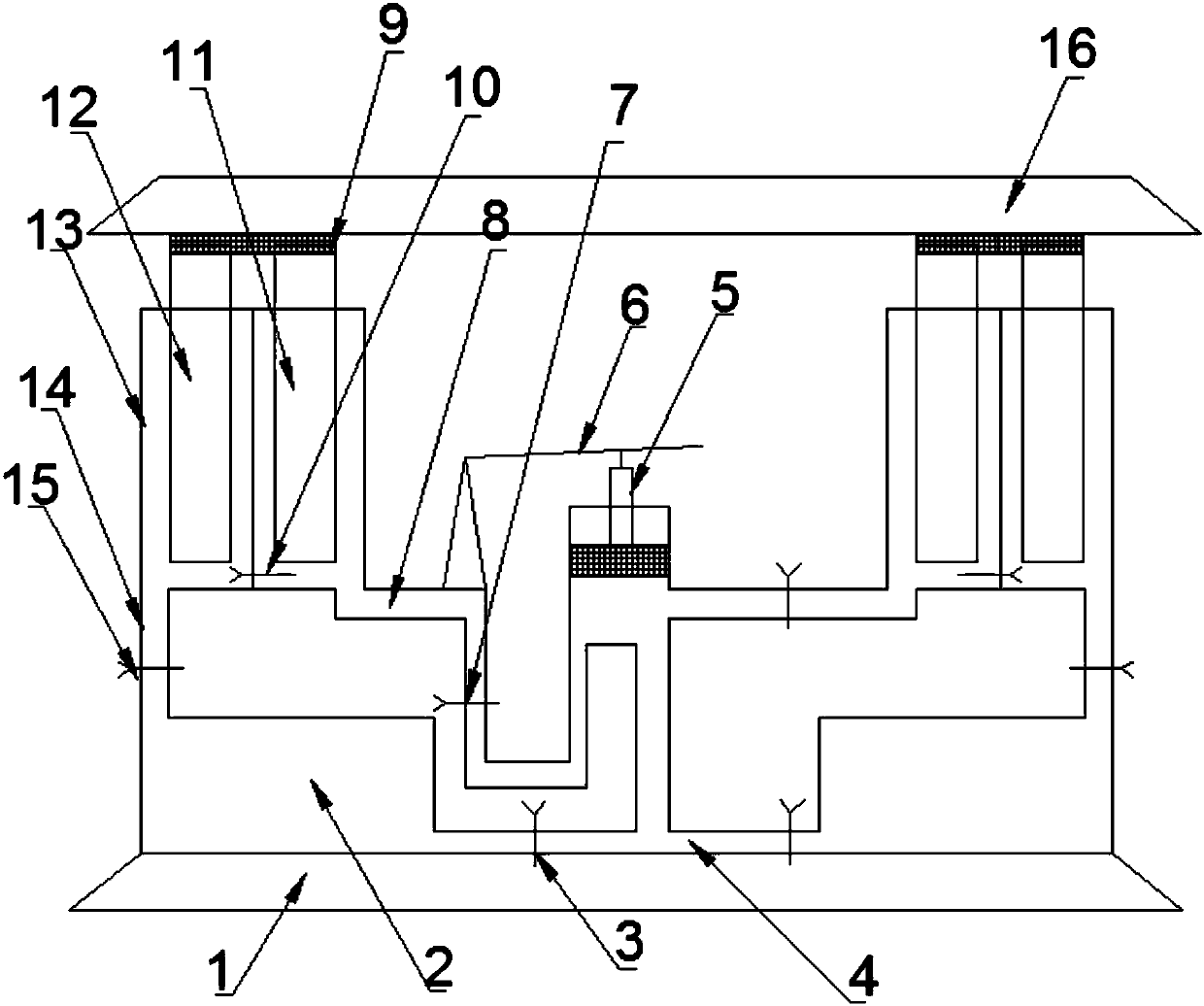
[0017] Such as figure 1 As shown, a support frame for manual height adjustment, the lift plate includes an upper lift plate 16 and a lower lift plate 1, and the support frame includes a symmetrically arranged oil storage tank 2 and a symmetrically arranged oil cylinder 13 for supporting the upper lift plate 16 , the support frame is located on the lower lifting plate 1, the oil cylinder 13 includes one or more independent cylinders, a starting device is arranged between the oil cylinders 13, and an oil inlet pipe 14 and an outlet pipe 14 are connected to the oil storage tank 2. Oil pipe 4, the oil cylinder 13 is connected to the oil storage tank 2 through the oil inlet pipe 14, the starting device is connected to the oil storage tank 2 through the oil outlet pipe 4, and the starting device is connected to the oil cylinder 13 through the oil pipe 8, the oil inlet pipe 14, the oil outlet pipe 4, The oil pipe 8 is respectively provided with a valve b15, a valve c3 and a valve d7....
Embodiment 2
[0020] As a special example of the first embodiment, the cylinder 13 in the first embodiment is provided with a cylinder a and a cylinder b, the cylinder a and the cylinder b are respectively provided with a piston a11 and a piston b12, and the cylinder a It communicates with cylinder b through valve a10.
[0021] In this embodiment, two cylinders are arranged in the oil cylinder 13. When the pressure in the oil cylinder 13 is increased, the cylinder a and the cylinder b increase the pressure at the same time, pushing the piston a11 and the piston b12 to move upward to play a supporting role. The function of a10, cylinder a and cylinder b are independent cylinders, and when a certain cylinder fails, the other cylinder can be guaranteed to continue to use.
Embodiment 3
[0023] In order to facilitate the control effect of the valve, the valve a10 described in the second embodiment is a rotary valve, so as to facilitate the control of the pressures in the piston a11 and the piston b12 to keep relatively independent.
PUM
 Abstract
Description
Claims
Application Information
 - R&D Engineer
- R&D Manager
- IP Professional
- Industry Leading Data Capabilities
- Powerful AI technology
- Patent DNA Extraction
Browse by: Latest US Patents, China's latest patents, Technical Efficacy Thesaurus, Application Domain, Technology Topic, Popular Technical Reports.
© 2024 PatSnap. All rights reserved.Legal|Privacy policy|Modern Slavery Act Transparency Statement|Sitemap|About US| Contact US: help@patsnap.com