
Time Domain Depth Sensor

A sensor and depth technology, used in electrical/magnetic depth measurement, electromagnetic measurement devices, agricultural machinery and implements, etc., can solve problems such as reducing crop yield and inaccurate depth measurement

Active Publication Date: 2021-11-02
DEERE & CO
View PDF9 Cites 0 Cited by
  • Summary
  • Abstract
  • Description
  • Claims
  • Application Information

AI Technical Summary

Problems solved by technology

For example, certain mechanical devices such as feeler gauges, potentiometers, linear position sensors, and ultrasonic rangefinders are prone to inaccurate depth measurements, which tends to reduce yields of crops planted at inaccurate seed depths

Method used


Image

  • Time Domain Depth Sensor
  • Time Domain Depth Sensor
  • Time Domain Depth Sensor

Examples


Embodiment Construction

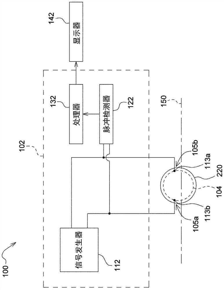
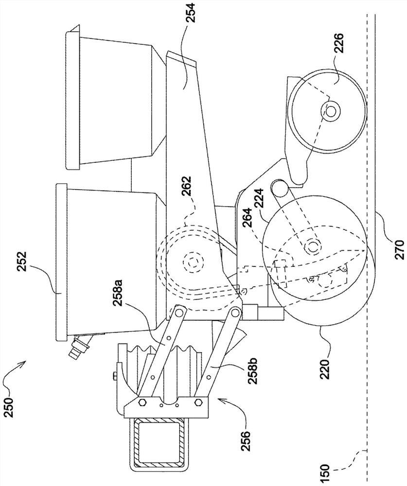
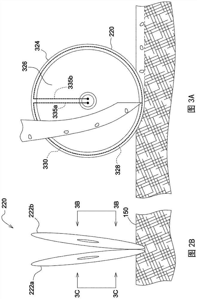
[0017] refer to Figure 1 to Figure 2B , shows sensor system 100 in combination with planter system 250, as shown, planter system 250 may include A row unit of planters traveling across a field while traveling. In other embodiments, sensor system 100 may also be used with air seeders, grain drills, tillage units, or in conjunction with figure 1 (It is only an exemplary embodiment) in other similar agricultural equipment.

[0018] exist figure 1 , a block diagram of one embodiment of a sensor system 100 is shown. In some embodiments, the sensor system 100 may include a time domain sensing unit 102 electrically coupled to a signal transmission element 104 disposed on the soil engaging device 220 . For example, time domain sensing unit 102 may include signal generator 112 , pulse detector 122 , processor 132 and display 142 . As depicted, signal generator 112 may be electrically coupled to first end 105b of signal transmission element 104 via first contact 113a such that a s...


PUM


Abstract

Embodiments herein relate to time domain depth sensor systems and methods for determining the depth of a ground engaging device in soil. The sensor system may comprise a signal transmission element arranged on the periphery of the ground engaging means adapted to penetrate the soil. The signal transmission element may be arranged to receive and transmit an electrical signal detected by the pulse detector in response to the impedance discontinuity. The pulse detector is configured to detect first and second reflected signals corresponding to sensed impedance discontinuities at the first soil location and the second soil location. An electrical data processor is communicatively coupled to the pulse detector and configured to determine a depth of the ground engaging device in the soil based on a difference between a first time of travel of the first reflected signal and a second time of travel of the second reflected signal.

Description

technical field [0001] The present disclosure generally relates to a time domain depth sensor system for determining the depth of a ground engaging device in soil. Background technique [0002] In agricultural production, it is very important to maintain optimal soil conditions to maximize crop yields. By maintaining optimal soil conditions, crops are able to receive sufficient nutrients that are essential for healthy growth, which in turn leads to sustained crop production. Examples of good soil quality may include, for example, good soil tillage, proper planting depth, restricted phytopathogens, and good soil drainage, where the absence of any of these conditions can result in improper germination. For example, at shallower trench depths, greater humidity fluctuations and temperature fluctuations may be experienced, causing crop damage. Therefore, in agricultural production, there is an increasing demand for agricultural equipment and systems capable of monitoring soil c...

Claims


Application Information

Patent Timeline
Patent Type & Authority Patents(China)
IPC IPC(8): G01B7/26
CPCG01B7/26A01B63/1112A01B79/005A01C7/203A01B47/00
Inventor 迈克尔·L·罗得斯卡思克·卡尔纳尼古拉·泰维斯杰弗里·S·普哈拉诺埃尔·W·安德森
Owner DEERE & CO
Learn More