
Guide limiting bracket device and system thereof

A limit bracket and guide technology, applied in measuring devices, pipeline brackets, mechanical devices, etc., can solve the problems of bending offset, the support effect cannot meet the requirements, and can not meet the requirements, and achieve the effect of guiding and limiting effect.

Pending Publication Date: 2018-05-08
BEIJING HUAFU ENG
View PDF0 Cites 2 Cited by
  • Summary
  • Abstract
  • Description
  • Claims
  • Application Information

AI Technical Summary

Problems solved by technology

At present, the existing spring support is only used as a variable force load-bearing frame, which cannot meet the use under various working conditions in actual situations. When the pipeline has lateral displacement, the existing spring support cannot be used at all. Under the lateral thrust of the pipeline, bending and offset will occur due to the existence of lateral thrust, so that the supporting effect cannot meet the requirements, and dangerous accidents are prone to occur

Method used


Image

  • Guide limiting bracket device and system thereof
  • Guide limiting bracket device and system thereof
  • Guide limiting bracket device and system thereof

Examples


Embodiment 1

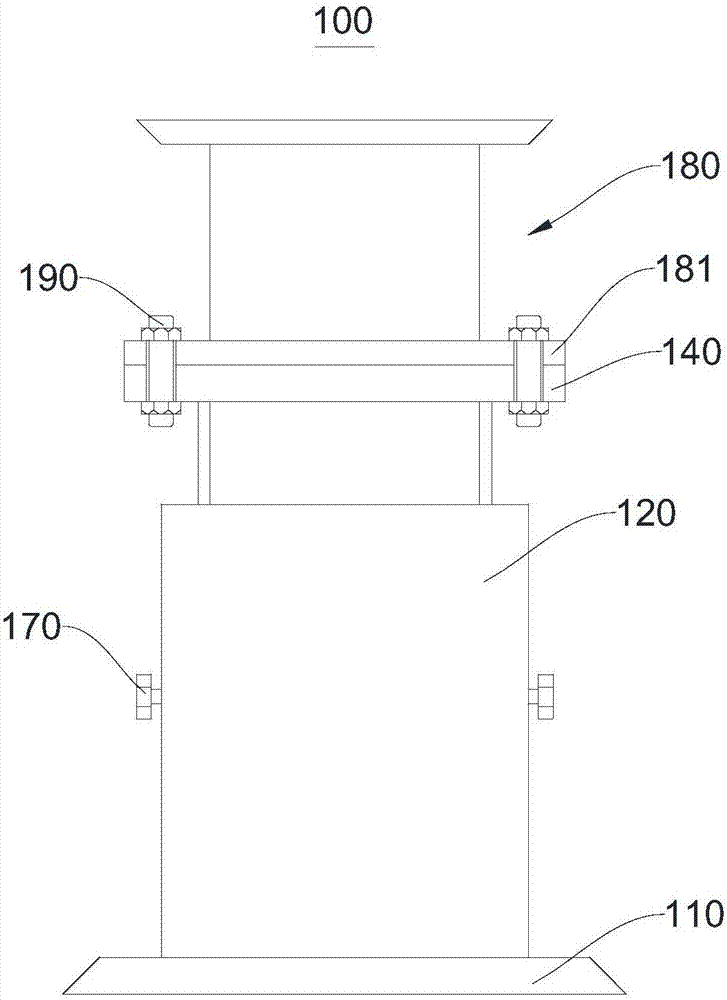
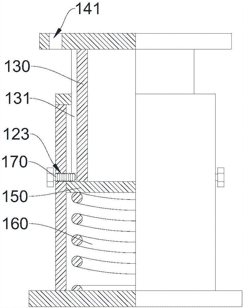
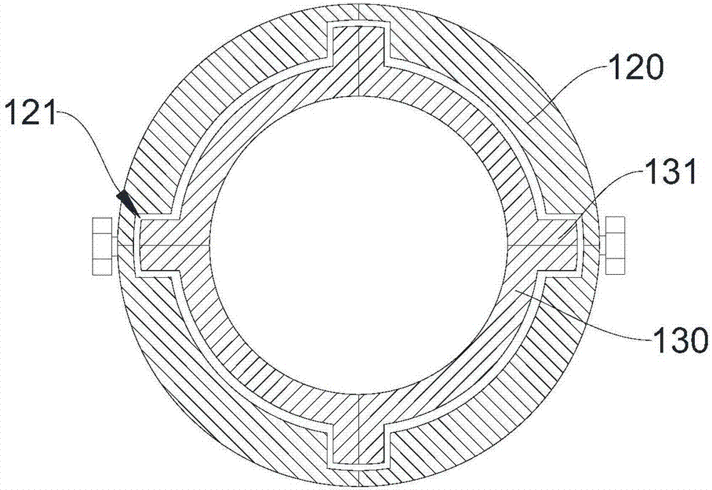
[0035] Please refer to figure 1 , this embodiment provides a guide and limit bracket device 100, including a bottom plate 110, a cylinder 120, a load column 130, a load plate 140, an indicator plate 150 and a spring 160, one end of the cylinder 120 is connected to the bottom plate 110, and the other end is provided with There is an opening, the spring 160 is arranged in the cylinder body 120 , the load plate 140 and the indicator plate 150 are respectively connected with both ends of the load column 130 , and the indicator plate 150 extends into the cylinder body 120 through the opening.

[0036] In this embodiment, the cylinder 120 is a cylinder with an opening at one end and a cavity inside. In other embodiments of the present invention, the cylindrical body 120 may be a rectangular body with openings at both ends and a cavity inside, and the external shape of the cylindrical body 120 may also be other shapes, which are not limited in the present invention. One end of the c...

Embodiment 2

[0044] This embodiment provides a guide and limit bracket device 200 .

[0045] The difference between the guide limit bracket device 200 and the guide limit bracket device 100 mainly lies in:

[0046] The outer surface of the cylinder body 120 is provided with a scale plate 125 for indicating the displacement range of the indicator plate 150 . Specifically, the cylinder body 120 is provided with a first through hole 127 , and in this embodiment, the first through hole 127 is a rectangle. The scale plate 125 is disposed beside the first through hole 127 and matches with the first through hole 127 . The indicator board 150 is provided with an indicator pin 151 , and the indicator pin 151 extends out of the first through hole 127 . The movement range of the indicator board 150 is known by the position indicated by the indicator needle 151 .

[0047] This embodiment provides a guide limit bracket system based on the guide limit bracket device 200 , including a pipe, a fixing d...


PUM


Abstract

The invention provides a guide limiting bracket device and a system thereof, and belongs to the technical field of pressure pipeline brackets. The guide limiting bracket device comprises a bottom plate, a cylinder, a loading column, a loading plate, an indicator plate and a spring, wherein one end of the cylinder is connected with the bottom plate, an opening is formed in the other end of the cylinder, a cavity is formed in the cylinder, the spring is arranged in the cavity, and the extension direction of the spring is consistent with the axial direction of the cylinder; one end of the loadingcolumn is connected with the loading plate, the other end of the loading column is connected with the indicator plate, and the indicator plate extends into the cavity from the opening and then is connected with one end, which is far from the bottom plate, of the spring. The device has the advantages of simple structure, convenience in operation, good pipeline fixing effect and high safety.

Description

technical field [0001] The present invention relates to the technical field of pressure pipeline supports, in particular, to a guide and limit support device and a system thereof. Background technique [0002] Petroleum and petroleum and petrochemical products are an important strategic resource, and the petroleum and petrochemical industry is a strategic pillar industry of China's national economy. With the rapid development of China's economy, the demand for energy is increasing. As an important part of energy, the proportion of oil in China's primary energy consumption is rising rapidly. Oil has become one of the important factors affecting China's economic growth. . Pipelines play an important role in the petrochemical industry and directly affect the production of petrochemicals. [0003] In the production equipment of the petrochemical industry, especially the pipelines for high-temperature material transportation, due to the large vertical thermal displacement, many...

Claims


Application Information

Patent Timeline
Patent Type & Authority Applications(China)
IPC IPC(8): F16L3/16F16L3/00G01B5/02
CPCF16L3/16F16L3/00G01B5/02
Inventor 翟徐炯王彦芳顾比伦王俊玲张鸿达訚俊锋杨珊
Owner BEIJING HUAFU ENG
Learn More