Injection molding piece cooling box

A cooling box and injection molding technology, applied in the field of injection molding processing, can solve the problems of accelerating the cooling of injection molding, spending a lot of time, low efficiency, etc., and achieve the effect of saving energy and reducing the loss of cold air

Inactive Publication Date: 2018-05-08
WUHU RONGJI IND
View PDF3 Cites 1 Cited by
  • Summary
  • Abstract
  • Description
  • Claims
  • Application Information

AI Technical Summary

Problems solved by technology

[0002] Injection molded parts will have a certain temperature after injection molding. Usually, they are allowed to dry by themselves, but this method takes too long. If the processing is fast, subsequent packaging will take a lot of time, so a kind of The cooling device cools the injection molded parts. For example, the application number is CN201620751379.4, which discloses a cooling machine for injection molded parts. The lower pressing plate is connected with the lower pressing plate, which can move up and down along the guide column. There is a cylinder in the body, and the cylinder shaft of the cylinder is fixedly connected with the bottom of the lower pressing plate. The upper surface of the formwork and the lower surface of the lower formwork are respectively fixed with condensation pipes
The cooling machine for injection molded parts drives the lower platen to press through the control cylinder, drives the upper template and the lower template to press the injection molded parts, and at the same time, the circulating water flow in the condensation pipe continuously flows into the cold water to take away the heat, accelerates the cooling of the injection molded parts, and the circulating water flow brings The lost heat can be recycled, which greatly saves the production cost, and condenses at the same time of pressing, which greatly shortens the processing time, but this kind of cooler can only cool one injection molded part at a time, and it is impossible to know whether the cooling is completed in time, and the efficiency low, cumbersome to operate

Method used


Image

  • Injection molding piece cooling box
  • Injection molding piece cooling box
  • Injection molding piece cooling box

Examples


Embodiment Construction

[0015] In order to make the technical means, creative features, goals and effects achieved by the present invention easy to understand, the present invention will be further described below in conjunction with specific embodiments.

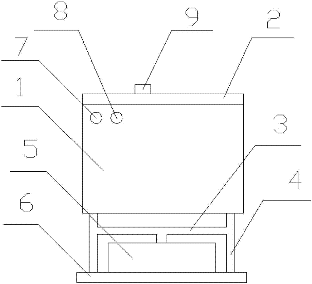
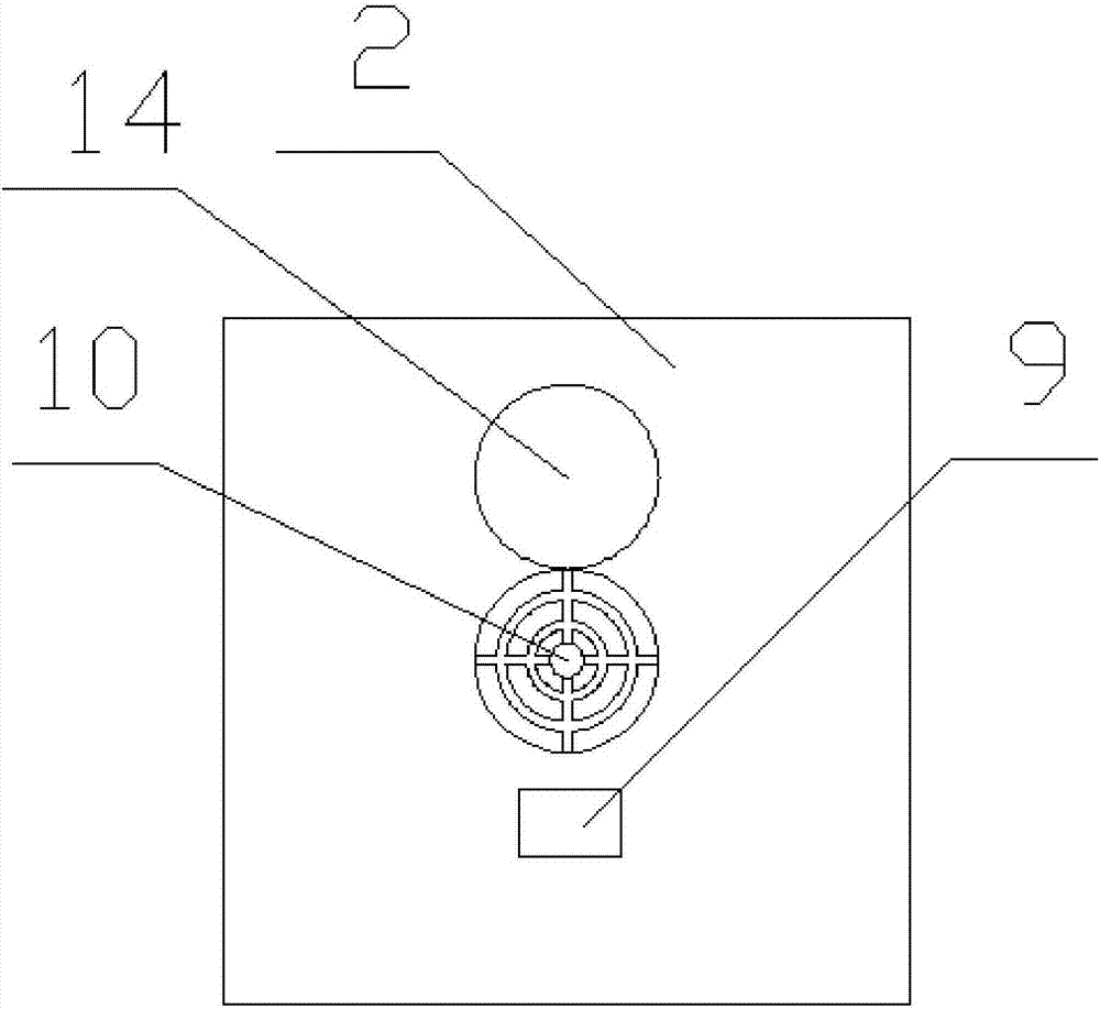
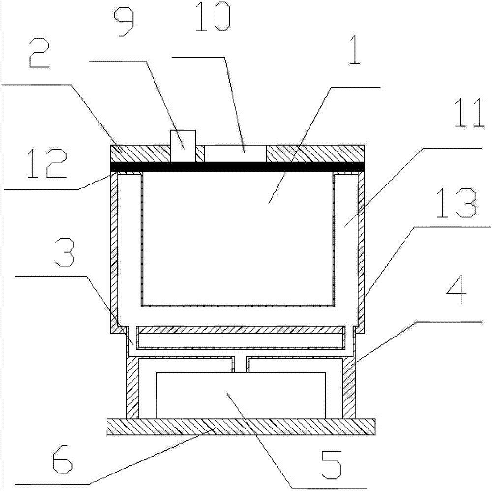
[0016] like Figure 1 to Figure 3 As shown, a cooling box for injection molded parts includes a cooling box body 1, a box cover 2, a support leg 4 and a cooling machine 5, the box cover 2 is hingedly arranged above the cooling box body 1, and the front The center is provided with an exhaust hole 10 with a hole cover 14, which can discharge the hot air sheet of the injection molded part at the beginning and speed up the cooling efficiency. A control box 9 is provided above the box cover 2, and a control box 9 is provided inside the control box 9. An infrared temperature detector and a microprocessor, the infrared temperature detector is used to detect the temperature in the cooling box, the microprocessor is a kind of 8-bit single-chip microcompute...


PUM


Abstract

The invention discloses an injection molding piece cooling box, and relates to the technical field of injection molding piece machining. The injection molding piece cooling box comprises a cooling boxbody, a box cover, supporting legs and a cooling machine. The box cover is hinged to the upper portion of the cooling box body. An exhaust hole with a hole cover is formed right in the center of thebox cover. A control box is arranged above the box cover. An infrared temperature detector and a microprocessor are arranged in the control box. A cooling inner container is arranged in the cooling box body and provided with a small hole. The cooling machine is arranged below the cooling box body. The supporting legs are arranged at the bottom of the cooling box body, and an air conveying pipe isconnected between the supporting legs and the cooling machine and communicates with the cooling inner container through the interiors of the supporting legs. The microprocessor is connected with the infrared temperature detector. The cooling box can cool a plurality of injection molding pieces at the same time, the cooling progress can be detected, and the injection molding piece cooling box is very practical.

Description

technical field [0001] The invention relates to the technical field of injection molded parts processing, in particular to a cooling box for injection molded parts. Background technique: [0002] Injection molded parts will have a certain temperature after injection molding. Usually, they are allowed to dry by themselves, but this method takes too long. If the processing is fast, subsequent packaging will take a lot of time, so a kind of The cooling device cools the injection molded parts. For example, the application number is CN201620751379.4, which discloses a cooling machine for injection molded parts. The lower pressing plate is connected with the lower pressing plate, which can move up and down along the guide column. There is a cylinder in the body, and the cylinder shaft of the cylinder is fixedly connected with the bottom of the lower pressing plate. The upper surface of the formwork and the lower surface of the lower formwork are respectively fixedly provided with...

Claims


Application Information

Patent Timeline
IPC IPC(8): B29C45/72
Inventor 李俊超
Owner WUHU RONGJI IND
Why Eureka
Try Eureka